 |
arnffw00001875
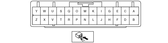
4x4 CONTROL MODULE INSPECTION [AT]
id0318008049d5
1. Remove the lower panel. (See LOWER PANEL REMOVAL/INSTALLATION.)
2. Turn the engine switch to the ON position (Engine off).
3. Attach the tester lead to the control module connector and inspect the voltage and continuity according to the Terminal Voltage Table (Reference).
Terminal Voltage Table (Reference)
arnffw00001875
|
|
Terminal |
Signal name |
Connected to |
condition |
Voltage (V) |
Inspection item(s) |
|---|---|---|---|---|---|
|
A
|
Motor control (4L-4H-2H)
|
Motor component (shift motor)
|
Motor operating
|
Below 1.0
|
• Inspect related wiring harness
• Motor component (shift motor)
|
|
Motor not operating
|
B+
|
||||
|
B
|
Motor control (4L-4H-2H)
|
Motor component (shift motor)
|
Motor operating
|
Below 1.0
|
• Inspect related wiring harness
• Motor component (shift motor)
|
|
Motor not operating
|
B+
|
||||
|
C
|
Motor control (2H-4H-4L)
|
Motor component (shift motor)
|
Motor operating
|
Below 1.0
|
• Inspect related wiring harness
• Motor component (shift motor)
|
|
Motor not operating
|
B+
|
||||
|
D
|
Motor control (2H-4H-4L)
|
Motor component (shift motor)
|
Motor operating
|
Below 1.0
|
• Inspect related wiring harness
• Motor component (shift motor)
|
|
Motor not operating
|
B+
|
||||
|
E
|
Neutral signal
|
Digital TR sensor
|
N position
|
Below 1.0
|
• Inspect related wiring harness
• Digital TR sensor
|
|
Except N position
|
Approx. 4.3
|
||||
|
F
|
4H or 4L mode signal
|
4x4 switch
|
2H or 4H position
|
B+
|
• Inspect related wiring harness
• 4x4 switch
|
|
4L position
|
Below 1.0
|
||||
|
G
|
2H or 4H mode signal
|
4x4 switch
|
2H position
|
Below 1.0
|
• Inspect related wiring harness
• 4x4 switch
|
|
4H or 4L position
|
B+
|
||||
|
H
|
Position 4
|
Motor component (position sensor)
|
2H position
|
Approx. 5.0
|
• Inspect related wiring harness
• Motor component (position sensor)
|
|
4H position
|
Approx. 5.0
|
||||
|
4L position
|
Approx. 4.2
|
||||
|
I
|
Position 2
|
Motor component (position sensor)
|
2H position
|
Approx. 5.0
|
• Inspect related wiring harness
• Motor component (position sensor)
|
|
4H position
|
Approx. 5.0
|
||||
|
4L position
|
Approx. 4.2
|
||||
|
J
|
Position 1
|
Motor component
|
2H position
|
Approx. 5.0
|
• Inspect related wiring harness
• Motor component (position sensor)
|
|
4H position
|
Approx. 5.0
|
||||
|
4L position
|
Below 1.0
|
||||
|
K
|
—
|
—
|
—
|
—
|
—
|
|
L
|
Position 3
|
Motor component (position sensor)
|
2H position
|
Approx. 5.0
|
• Inspect related wiring harness
• Motor component (position sensor)
|
|
4H position
|
Approx. 5.0
|
||||
|
4L position
|
Approx. 4.2
|
||||
|
M
|
Vehicle speed
|
Speed sensor
|
Engine switch OFF
|
Below 1.0
|
• Inspect related wiring harness
• Speed sensor
|
|
Engine switch ON
|
Approx. 5.0
|
||||
|
N
|
Ground
|
Speed sensor or motor component
|
Engine switch OFF
|
Below 1.0
|
• Inspect related wiring harness
• Speed sensor
• Motor component
|
|
Engine switch ON
|
Approx. 5.0
|
||||
|
O
|
—
|
—
|
—
|
—
|
—
|
|
P
|
—
|
—
|
—
|
—
|
—
|
|
Q
|
DTC output
|
Data link connector (DLC)
|
Engine switch OFF
|
Below 1.0
|
• Inspect related wiring harness
|
|
Engine switch ON
|
Approx. 5.0
|
||||
|
R
|
4x4 indicator light
|
4x4 indicator light
|
4x4 indicator light OFF
|
B+
|
• Inspect related wiring harness
• 4x4 indicator light
|
|
4x4 indicator light ON
|
Below 1.0
|
||||
|
S
|
4L indicator light
|
4L indicator light
|
4L indicator light OFF
|
B+
|
• Inspect related wiring harness
• 4L indicator light
|
|
4L indicator light ON
|
Below 1.0
|
||||
|
T
|
IG 1
|
Engine fuse
|
Engine switch OFF
|
Below 1.0
|
• Inspect related wiring harness
• Engine fuse
|
|
Engine switch ON
|
B+
|
||||
|
U
|
Clutch coil
|
Clutch coil
|
Clutch coil operating
|
B+
|
• Inspect related wiring harness
• Clutch coil
|
|
Clutch coil not operating
|
Below 1.0
|
||||
|
V
|
Lock solenoid valve
|
Lock solenoid valve
|
Lock solenoid valve operating
|
Below 1.0
|
• Inspect related wiring harness
• Lock solenoid valve
|
|
Lock solenoid valve not operating
|
B+
|
||||
|
W
|
Ground
|
Body ground
|
Under any condition
|
Below 1.0
|
• Inspect related wiring harness
(W—ground)
|
|
X
|
Ground
|
Body ground
|
Under any condition
|
Below 1.0
|
• Inspect related wiring harness
(X—ground)
|
|
Y
|
B+
|
PTC/AT fuse
|
Engine switch OFF
|
B+
|
• Inspect related wiring harness
|
|
Engine switch ON
|
|||||
|
Z
|
B+
|
PTC/AT fuse
|
Engine switch OFF
|
B+
|
• Inspect related wiring harness
|
|
Engine switch ON
|