 |
dbr411zwb018
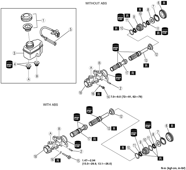
MASTER CYLINDER DISASSEMBLY/ASSEMBLY
id041100803100
1. After removing the brake fluid, disassemble in the order indicated in the table.
2. Assemble in the reverse order of disassembly.
dbr411zwb018
|
|
1
|
Cap set
|
|
2
|
Pin
|
|
3
|
Reservoir
|
|
4
|
Joint bushing
|
|
5
|
Brake fluid level sensor
|
|
6
|
Seal and plate assembly
|
|
7
|
Snap ring
|
|
8
|
Spacer
|
|
9
|
Piston guide
|
|
10
|
O-ring
|
|
11
|
Cup
|
|
12
|
Primary piston stopper
|
|
13
|
Primary piston
|
|
14
|
Stop screw (without ABS)
|
|
15
|
Stop screw (with ABS)
|
|
16
|
Gasket
|
|
17
|
Secondary piston
|
|
18
|
Master cylinder body
|
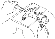
Stop Screw (with ABS) Assembly Note
1. Install the secondary piston component with the piston hole facing the stop screw.
2. Install and tighten a new gasket and the stop screw.
3. Push and release the piston to verify that it is held by the stop screw.
a6e6912w043
|
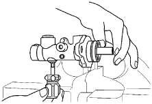
Stop Screw (without ABS) Assembly Note
1. Push the primary piston component in fully.
a6e6912w025
|
2. Install and tighten a new gasket and the stop screw.
3. Push and release the piston to verify that it is held by the stop screw.