 |
absggw00000810
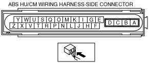
ABS HU/CM INSPECTION
id041300801000
1. Disconnect the ABS HU/CM connector.
2. Connect the negative battery cable.
3. Attach the tester lead to the ABS HU/CM harness side connector, then inspect voltage, continuity or resistance according to the standard (reference value) on the table.
Standard (Reference Value)
absggw00000810
|
|
Terminal |
Signal name |
Connected to |
Measured item |
Measured terminal (measured condition) |
Standard |
Inspection item(s) |
|---|---|---|---|---|---|---|
|
A
|
Ground
(ABS motor)
|
Ground point
|
Continuity
|
A—ground point
|
Continuity detected
|
• Wiring harness (A—ground point)
|
|
B
|
Power supply
(ABS motor operation)
|
Battery
|
Voltage
|
Under any condition
|
B+
|
• Wiring harness (B—battery)
|
|
C
|
Power supply
(solenoid)
|
Battery
|
Voltage
|
Under any condition
|
B+
|
• Wiring harness (C―battery)
|
|
D
|
Ground
(ABS system)
|
Ground point
|
Continuity
|
D—ground point
|
Continuity detected
|
• Wiring harness (D—ground point)
|
|
E
|
LF wheel-speed sensor (signal)
|
LF ABS wheel-speed sensor
|
Continuity
|
E—LF ABS wheel-speed sensor connector terminal A
|
Continuity detected
|
• Wiring harness (E—LF ABS wheel-speed sensor connector terminal A)
|
|
F
|
LF wheel-speed sensor (ground)
|
LF ABS wheel-speed sensor
|
Continuity
|
F—LF ABS wheel-speed sensor connector terminal B
|
Continuity detected
|
• Wiring harness (F—LF ABS wheel-speed sensor connector terminal B)
|
|
G
|
LR wheel-speed sensor (ground)
|
LR ABS wheel-speed sensor
|
Continuity
|
G—LR ABS wheel-speed sensor connector terminal B
|
Continuity detected
|
• Wiring harness (G—LR ABS wheel-speed sensor connector terminal B)
|
|
H
|
—
|
—
|
—
|
—
|
—
|
—
|
|
I
|
LR wheel-speed sensor (signal)
|
LR ABS wheel-speed sensor
|
Continuity
|
I—LR ABS wheel-speed sensor connector terminal A
|
Continuity detected
|
• Wiring harness (I—LR ABS wheel-speed sensor connector terminal A)
|
|
J
|
Power supply
(system)
|
Ignition switch or engine switch
|
Voltage
|
Ignition switch or engine switch at ON
|
B+
|
• Wiring harness (J—ignition switch or engine switch)
|
|
Ignition switch or engine switch is off.
|
1 V or less
|
—
|
||||
|
K
|
RR wheel-speed sensor (ground)
|
RR ABS wheel-speed sensor
|
Continuity
|
K—RR ABS wheel-speed sensor connector terminal B
|
Continuity detected
|
• Wiring harness (K—RR ABS wheel-speed sensor connector terminal B)
|
|
L
|
RR wheel-speed sensor (signal)
|
RR ABS wheel-speed sensor
|
Continuity
|
L—RR ABS wheel-speed sensor connector terminal A
|
Continuity detected
|
• Wiring harness (L—RR ABS wheel-speed sensor connector terminal A)
|
|
M
|
RF wheel-speed sensor (ground)
|
RF ABS wheel-speed sensor
|
Continuity
|
M—RF ABS wheel-speed sensor connector terminal B
|
Continuity detected
|
• Wiring harness (M—RF ABS wheel-speed sensor connector terminal B)
|
|
N
|
Brake switch
|
Brake switch
|
Voltage
|
N—brake switch
(Brake pedal depressed)
|
B+
|
• Wiring harness (N—brake switch)
• Brake switch
|
|
Y—brake switch
(Brake pedal not depressed)
|
1 V or less
|
|||||
|
O
|
RF wheel-speed sensor (signal)
|
RF ABS wheel-speed sensor
|
Continuity
|
O—RF ABS wheel-speed sensor connector terminal A
|
Continuity detected
|
• Wiring harness (O—RF ABS wheel-speed sensor connector terminal A)
|
|
P*
|
G sensor (signal)
|
G sensor
|
Continuity
|
P—G sensor connector terminal B
|
Continuity detected
|
• Wiring harness (P—G sensor connector terminal B)
|
|
Q
|
On-board diagnostic
|
KLN terminal of DLC-2
|
Continuity
|
Q—DLC-2 connector terminal KLN
|
Continuity detected
|
• Wiring harness (Q—DLC-2 connector terminal KLN)
|
|
R
|
—
|
—
|
—
|
—
|
—
|
—
|
|
S
|
—
|
—
|
—
|
—
|
—
|
—
|
|
T
|
—
|
—
|
—
|
—
|
—
|
—
|
|
U
|
—
|
—
|
—
|
—
|
—
|
—
|
|
V*
|
G sensor (power supply
|
G sensor
|
Continuity
|
V—G sensor connector terminal A
|
Continuity detected
|
• Wiring harness (V—G sensor connector terminal A)
|
|
W*
|
G sensor (ground)
|
G sensor
|
Continuity
|
W—G sensor connector terminal C
|
—
|
• Wiring harness (W—G sensor connector terminal C)
|
|
X
|
—
|
—
|
—
|
—
|
—
|
—
|
|
Y
|
—
|
—
|
—
|
—
|
—
|
—
|
|
Z
|
—
|
—
|
—
|
—
|
—
|
—
|