 |
dbr413zwb014
REAR ABS WHEEL-SPEED SENSOR INSPECTION
id041300801200
Visual Inspection
1. Inspect the sensor for looseness and damage. Replace the sensor if necessary.
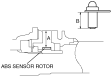
Clearance Inspection
1. Remove the ABS wheel-speed sensor.
2. Measure the length A and B shown in the figure using vernier calipers.
dbr413zwb014
|
3. Subtract B from A then verify the clearance between the wheel-speed sensor and the sensor rotor.
Resistance Inspection
1. Disconnect the ABS wheel‐speed sensor connector.
2. Inspect the resistance at the ABS wheel‐speed sensor.
Voltage Inspection
1. On level ground, jack up the vehicle and support it evenly on safety stands.
2. Disconnect the ABS wheel‐speed sensor connector.
3. Inspect each sensor by rotating each wheel one revolution per second.
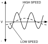
Voltage Pattern Inspection
1. Jack up the vehicle on level ground and support it evenly on safety stands.
2. Disconnect the ABS wheel‐speed sensor connector.
3. Using an oscilloscope, inspect voltage pattern for distortion and noise by rotating each wheel.
dbr413zwb011
|