 |
arnffw00000432
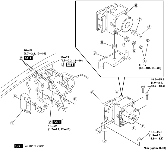
ABS HU/CM REMOVAL/INSTALLATION
id041300801400
1. Remove in the order indicated in the table.
2. Install in the reverse order of removal.
L.H.D.
arnffw00000432
|
R.H.D.
absggw00000721
|
|
1
|
Connector
(See Connector Removal Note.)
(See Connector Installation Note.)
|
|
2
|
Brake pipe
(See Brake Pipe Removal Note.)
|
|
3
|
ABS HU/CM component
|
|
4
|
Nut
|
|
5
|
washer
|
|
6
|
ABS HU/CM
|
|
7
|
Bushing (ABS HU/CM side)
|
|
8
|
Bushing (bracket side)
|
|
9
|
Bracket
|
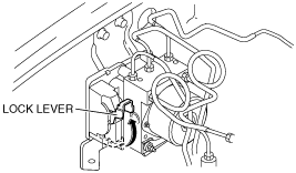
Connector Removal Note
1. Rotate the lock lever in the direction of the arrow, and remove the ABS HU/CM connector.
absggw00000722
|
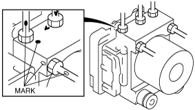
Brake Pipe Removal Note
1. Place an alignment mark on the brake pipe and ABS HU/CM.
absggw00000723
|
2. Apply protective tape to the connector to prevent brake fluid from entering.
3. Remove the brake pipe.
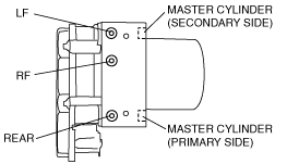
Brake Pipe Installation Note
1. When install the brake pipe, align the marks made before removal with the ABS HU/CM as shown in the figure.
absggw00000724
|
2. Tighten the brake pipe to the specified torque using the SST (49 0259 770B).
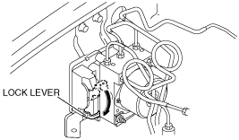
Connector Installation Note
1. After connecting the connector, rotate the lock lever in the direction of the arrow to install the ABS HU/CM connector.
absggw00000725
|