 |
absggw00000987
PID/DATA MONITOR INSPECTION [5R55S]
id0502c1805600
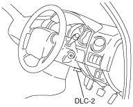
1. Connect the IDS/PDS to the DLC-2.
absggw00000987
|
2. After the vehicle is identified, select the following items from the initial screen of the IDS/PDS.
3. Select the PID from the PID table
4. Verify the PID data according to the directions on the IDS/PDS screen.
PID/DATA MONITOR AND RECORD function table
|
Monitor item |
Definition |
Unit/Condition |
Condition/Specification |
TCM terminal |
|---|---|---|---|---|
|
BPP
|
Brake switch
|
on/off
|
• Brake pedal depressed: on
• Other: off
|
N/A
|
|
FIRM_ST
|
Firm shaft control (FSC) status requested
|
0/1
|
• FSC not commanded by IDS/PDS PID output (off): 0
• FSC commanded by IDS/PDS PID output (on): 1
|
N/A
|
|
GEAR
|
Calculated gear range in TCM
|
1/2/3/4/5
|
• 1GR: 1
• 2GR: 2
• 3GR: 3
• 4GR: 4
• 5GR: 5
|
N/A
|
|
GEAR_OSC
|
PID used to command gear changes during Simulation Function
|
1/2/3/4/5
|
• 1GR: 1
• 2GR: 2
• 3GR: 3
• 4GR: 4
• 5GR: 5
|
N/A
|
|
ISS
|
ISS sensor
|
rpm
|
Indicates intermediate shaft speed
|
AM, AS
|
|
OSS
|
OSS sensor
|
rpm
|
Indicates output shaft speed
|
AD, AG
|
|
PCA
|
Pressure control solenoid A
|
psi
|
Indicates pressure control solenoid A commanded pressure
|
I, CK
|
|
PCB
|
Pressure control solenoid B
|
psi
|
Indicates pressure control solenoid B commanded pressure
|
J, CK
|
|
PCC
|
Pressure control solenoid C
|
psi
|
Indicates pressure control solenoid C commanded pressure
|
M, CK
|
|
RPM
|
Engine speed
|
rpm
|
Indicates engine speed
|
N/A
|
|
SSA
|
Shift solenoid A
|
on/off
|
• Shift solenoid A operation: on
• Shift solenoid A not operation: off
|
B, CK
|
|
SSB
|
Shift solenoid B
|
on/off
|
• Shift solenoid B operation: on
• Shift solenoid B not operation: off
|
C, CK
|
|
SSC
|
Shift solenoid C
|
on/off
|
• Shift solenoid C operation: on
• Shift solenoid C not operation: off
|
F, CK
|
|
SSD
|
Shift solenoid D
|
on/off
|
• Shift solenoid D operation: on
• Shift solenoid D not operation: off
|
D, CK
|
|
TCC
|
TCC control solenoid
|
%
|
Indicates TCC control solenoid operation
|
A, CK
|
|
TCCRAT
|
Torque converter speed ratio
|
ratio
|
Indicates torque converter speed ratio (engine speed compared with turbine shaft speed)
|
N/A
|
|
TFT
|
ATF temperature
|
°C, °F
|
Indicates ATF temperature
|
AY, BH
|
|
TR_D
|
Digital TR sensor signal
|
|
Indicates digital TR sensor signal
|
AX, BU, BY, CA
|
|
TR_V
|
Digital TR sensor signal voltage
|
V
|
Indicates digital TR sensor signal voltage
|
AX, BU, BY, CA
|
|
TR1
|
TR1 switch
|
0/1
|
• TR1 switch open: 1
• TR1 switch close: 0
|
BY
|
|
TR2
|
TR2 switch
|
0/1
|
• TR2 switch open: 1
• TR2 switch close: 0
|
BU
|
|
TSS
|
TSS sensor
|
rpm
|
Indicates turbine shaft speed
|
AH, AP
|
|
VSS
|
Vehicle speed
|
mph
|
Indicates vehicle speed
|
AD, AG
|
Simulation Function Procedure
1. Connect the IDS/PDS to the DLC-2.
absggw00000987
|
2. After the vehicle is identified, select the following items from the initial screen of the IDS/PDS.
3. Select the simulation items from the PID table.
4. Perform the simulation function, inspect the operations for each parts.
Simulation item table
|
Simulation item |
Applicable component |
Unit |
TCM terminal |
|---|---|---|---|
|
PCA
|
Pressure control solenoid A
|
pis
|
I, CK
|
|
PCB
|
Pressure control solenoid B
|
pis
|
J, CK
|
|
PCC
|
Pressure control solenoid C
|
pis
|
M, CK
|
|
SSA
|
Shift solenoid A
|
on/off
|
B, CK
|
|
SSB
|
Shift solenoid B
|
on/off
|
C, CK
|
|
SSC
|
Shift solenoid C
|
on/off
|
F, CK
|
|
SSD
|
Shift solenoid D
|
on/off
|
D, CK
|
|
TCC
|
TCC control solenoid
|
%
|
A, CK
|