 |
absggw00001756
MECHANICAL SYSTEM TEST [5R55S]
id0513c1249100
Mechanical System Test Preparation
1. Engage the parking brake and use wheel chocks at the front and rear of the wheels.
2. Inspect the engine coolant level. (See COOLING SYSTEM SERVICE WARNINGS [WL-C, WE-C].) (See ENGINE COOLANT LEVEL INSPECTION [WL-C, WE-C].)
3. Inspect the engine oil level. (See ENGINE OIL LEVEL INSPECTION [WL-C, WE-C].)
4. Inspect the ATF level. (See AUTOMATIC TRANSMISSION FLUID (ATF) INSPECTION [5R55S].)
5. Inspect the idle speed. (See ENGINE TUNE-UP [WL-C, WE-C].)
Line Pressure Test (Pressure Control A, Pressure Control B)
Pressure control A, pressure control B
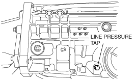
1. Remove the line pressure tap.
absggw00001756
|
2. Connect the pressure gauge (SST: 49 0378 400C) to the line pressure tap.
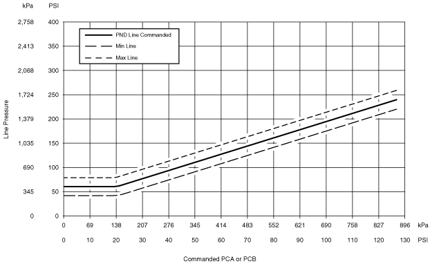
3. Connect the diagnostic scan tool and monitor the PC A and PC B PIDs. Note which PID is commanded higher. Use the higher commanded PC x value when referencing the Line Pressure Charts A and B.
4. Start the engine and check the line pressure reading from the gauge installed in Step 1. Refer to the Line Pressure Chart for the correct shift lever position.
Line pressure (pressure control A, pressure control B)
|
Position/range |
Line pressure (kPa {kgf/cm2, psi}) |
|
|---|---|---|
|
Idle |
Stall |
|
|
P/N
|
793 {8.09, 115}
|
793 {8.09, 115}
|
|
R
|
793 {8.09, 115}
|
2,138 {21.80, 310}
|
|
D, 3, 2, 1
|
793 {8.09, 115}
|
1,520 {15.47, 220}
|
absggw00001757
|
absggw00001758
|
5. Install the line pressure tap.
6. Go to the Pressure Control C Pressure Test in this section.
Pressure Control C
1. If not previously connected, install the scan tool.
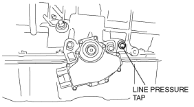
2. Remove the line pressure tap.
absggw00001759
|
3. Connect the pressure gauge (SST: 49 0378 400C) to the line pressure tap.
4. Using the diagnostic scan tool, monitor the PC C PID and note the commanded pressure.
5. Start the engine and check the PC C pressure.
Line pressure (pressure control C)
|
Position/range |
Line pressure (kPa {kgf/cm2, psi}) |
|
|---|---|---|
|
Idle |
Stall |
|
|
P/N
|
27 {0.28, 4}
|
0 {0, 0}
|
|
R
|
793 {8.09, 115}
|
793 {8.09, 115}
|
|
D, 3, 2, 1
|
27 {0.28, 4}
|
0 {0, 0}
|
6. Install the line pressure tap.
Line pressure diagnosis chart
|
Test Results |
Possible Source |
|---|---|
|
High at Idle—All Ranges
|
• Wiring harnesses
• PC C boost valve
• Pressure control solenoid C
• Main regulator valve
|
|
Low at Idle—All Ranges
|
• Low fluid level
• Fluid inlet filter/seal
• Control valve body
• Cross leaks
• Gaskets
• Pump
• Separator plate
|
|
Low—All Forward Ranges
|
• Forward Clutch
• Main Control
• Overdrive brake servo
• Intermediate brake servo
|
|
Low in P position Only
|
• Control valve body
|
|
Low in R position Only
|
• Separator plate
• Reverse servo piston, cover seal
• Reverse clutch
• Overdrive brake servo
• Intermediate brake servo
• Control valve body
• Forward clutch
|
|
Low in N position Only
|
• Control valve body
• Overdrive brake servo
• Intermediate brake servo
|
|
Low in D range
|
• Forward clutch
• Overdrive brake servo
• Intermediate brake servo
• Control valve body
|
|
Low in D range Only (O/D OFF mode)
|
• Forward clutch
• Overdrive brake servo
• Intermediate brake servo
• Control valve body
|
|
Low in 1 range
|
• Forward clutch
• Control valve body
|
|
Low in 2 range
|
• Intermediate brake servo
• Overdrive brake servo
• Forward clutch
|
|
Low in 3 range
|
• Intermediate brake servo
• Overdrive brake servo
• Forward clutch
|
Stall Speed Test
1. Connect a tachometer to the engine.
2. Depress the accelerator pedal to the floor (WOT) in each shift position. Record the rpm reached in each shift position.
Engine stall speed
|
Engine type |
rpm |
|---|---|
|
WL-C
|
2,700
|
|
WE-C
|
2,900
|
3. After testing the D, 3, 2, 1 range and R position, shift the selector lever to the N position and run the engine at 1,000 rpm for 15 s to allow the torque converter to cool before testing the next gear position.
Stall speed diagnosis chart
|
Position/range |
Stall speeds high |
Stall speeds low |
|---|---|---|
|
D, D (O/D OFF mode) and 1
|
• Overdrive one-way clutch
• Rear one-way clutch
|
—
|
|
D (O/D OFF mode), 2 and 1
|
• Forward clutch
• Overdrive one-way clutch
|
—
|
|
D
|
• Forward clutch
• Overdrive one-way clutch
|
—
|
|
D, D (O/D OFF mode), 2, 1 and R
|
• General pressure concerns
• Forward clutch
• Overdrive one-way clutch
|
• Converter one-way clutch or engine driveability concerns
|
|
R
|
• High/reverse
• High clutch
• Low/reverse band/servo
|
—
|
|
2
|
• Intermediate band/servo
|
—
|
|
1
|
• Intermediate band/servo
|
—
|
4. If the stall speed is too low, inspect the idle speed.