 |
absggw00001200
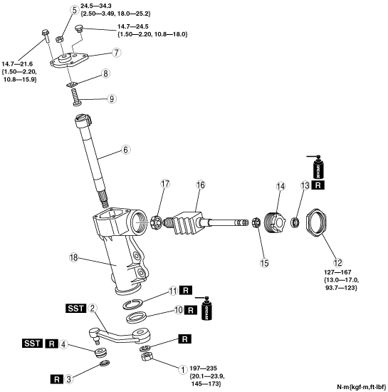
STEERING GEAR AND LINKAGE DISASSEMBLY/ASSEMBLY
id061100000600
1. Disassemble in the order indicated in the table.
2. Assemble in the reverse order of disassembly.
3. After assembly, adjust the steering gear backlash. (See STEERING GEAR AND LINKAGE INSPECTION.)
4. Add the specified steering gear oil.
absggw00001200
|
|
1
|
Nut
|
|
2
|
Pitman arm
(See Pitman Arm Disassembly Note.)
|
|
3
|
Clip
|
|
4
|
Dust boot
(See Dust Boot Disassembly Note.)
(See Dust Boot Assembly Note.)
|
|
5
|
Lock nut (side cover)
|
|
6
|
Sector shaft
(See Sector Shaft Assembly Note.)
|
|
7
|
Side cover
|
|
8
|
Adjusting shim
|
|
9
|
Adjusting screw
|
|
10
|
Oil seal
|
|
11
|
Retaining ring
|
|
12
|
Locknut
(See Locknut Disassembly Note.)
(See Locknut Assembly Note.)
|
|
13
|
Oil seal
|
|
14
|
Adjusting nut
|
|
15
|
Bearing
|
|
16
|
Worm shaft
|
|
17
|
Bearing
|
|
18
|
Gear housing
|
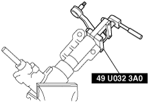
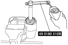
Pitman Arm Disassembly Note
1. Separate the pitman arm from the steering gear using the SST.
absggw00001201
|
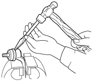
Dust Boot Disassembly Note
1. Place the chisel against the boot and hold it at the angle shown.
2. Remove the dust boot by tapping it with a hammer.
absggw00001202
|
Locknut (Side Cover), Sector Shaft Disassembly Note
1. Loosen the locknut.
2. Remove the side cover attaching bolts.
3. Set the sector shaft in the middle position.
4. Tap the sector shaft lower end using a plastic hammer to loosen the sector shaft.
5. Lift and remove the sector shaft with the locknut and the side cover from the gear housing.
absggw00001203
|
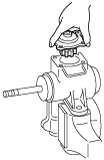
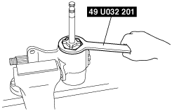
Locknut Disassembly Note
1. Remove the locknut using the SST.
absggw00001204
|
Adjusting Nut Disassembly Note
1. Remove the adjusting nut using the SST.
absggw00001205
|
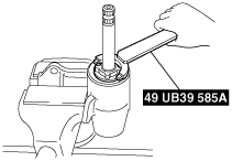
Locknut Assembly Note
1. Inspect the worm shaft preload using the SST.
absggw00001206
|
2. If not as specified, adjust the preload.
absggw00001207
|
absggw00001205
|
absggw00001207
|
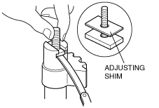
Sector Shaft Assembly Note
1. Set the adjusting screw and shim, in the “T” groove.
2. Measure the clearance in the axial direction.
absggw00001208
|
3. Adjust the clearance to the specified value if the clearance is more than the specified value
4. Assemble the sector shaft in such a way that the teeth of the sector shaft mesh with the center part of the teeth of the worm shaft.
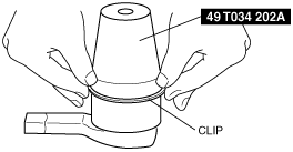
Dust Boot Assembly Note
1. Wipe the grease off the ball joint.
2. Put a small amount of lithium-based grease into a new dust boot.
3. Install the dust boot onto to the ball joint.
4. Set the SST over the boot and install a new clip.
absggw00001209
|
5. Wipe away excessive grease.