 |
arnffw00000314
POWER STEERING OIL PUMP DISASSEMBLY/ASSEMBLY [G6]
id0614008008f2
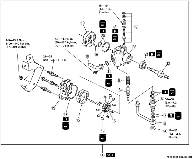
1. Disassemble in the order indicated in the table.
2. Assemble in the reverse order of disassembly.
3. After installing the P/S pump. flush the power steering system according to the following procedures.
arnffw00000314
|
|
1
|
Power steering oil pump component
|
|
2
|
Pressure switch component
|
|
3
|
O‐ring
|
|
4
|
Nut
|
|
5
|
Connector
|
|
6
|
Connector bolt
|
|
7
|
O‐ring
|
|
8
|
Control valve
|
|
9
|
Spring
|
|
10
|
Suction pipe
|
|
11
|
O‐ring
|
|
12
|
Shaft component
|
|
13
|
Rear pump body
|
|
14
|
O‐ring
|
|
15
|
Cam ring
|
|
16
|
Rotor
|
|
17
|
Vane
|
|
18
|
Pin
|
|
19
|
Side plate
(SeeSide Plate Assembly Note.)
|
|
20
|
O‐ring
|
|
21
|
Oil seal
|
|
22
|
Front pump body
|
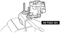
Power Steering Oil Pump Component Disassembly Note
1. Secure the power steering oil pump using the SST.
arnffw00000105
|
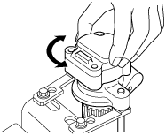
Side Plate Assembly Note
1. Install a new O-ring and the side plate to the front body.
2. Position the side plate using the rear body.
arnffw00000113
|
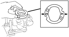
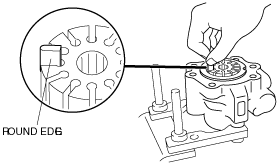
Vane, Rotor, Cam Ring Assembly Note
1. Install the cam ring with the marks facing the front body.
arnffw00000318
|
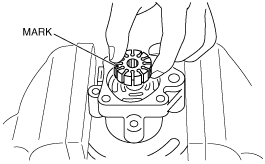
2. Install the rotor with the mark facing the rear body.
arnffw00000319
|
3. Install the vanes in the rotor with the rounded edges outward.
arnffw00000320
|