 |
absggw00001878
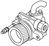
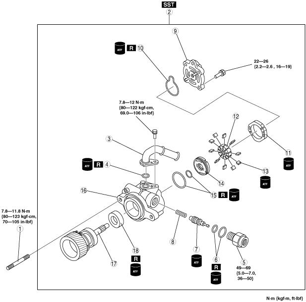
POWER STEERING OIL PUMP DISASSEMBLY/ASSEMBLY [WLT-1, WLT-2, WL-3, WL-C, WE-C]
id0614008008f3
1. Disassemble in the order indicated in the table.
2. Assemble in the reverse order of disassembly.
3. After installing the P/S pump. flush the power steering system according to the following procedures.
absggw00001878
|
|
1
|
Stud
(See Stud Disassembly Note.)
(See Stud Assembly Note.)
|
|
2
|
Power steering oil pump component
|
|
3
|
Suction pipe
|
|
4
|
O‐ring
|
|
5
|
Connector
|
|
6
|
O‐ring
|
|
7
|
Control valve
|
|
8
|
Spring
|
|
9
|
Rear pump body
(See Rear Pump Body Assembly Note.)
|
|
10
|
O‐ring
|
|
11
|
Cam ring
|
|
12
|
Rotor
|
|
13
|
Vane
|
|
14
|
Side plate
(See Side Plate Assembly Note.)
|
|
15
|
O‐rings
|
|
16
|
Front pump body
|
|
17
|
Gear shaft component
|
|
18
|
Oil seal
(See Oil Seal Disassembly Note.)
(See Oil Seal Assembly Note.)
|
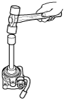
Stud Disassembly Note
1. Tighten 2 nuts against each other on the stud, and then remove it.
absggw00001879
|
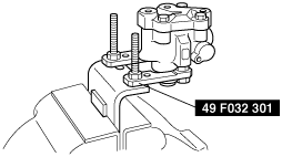
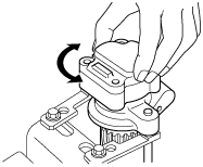
Power Steering Oil Pump Component Disassembly Note
1. Secure the power pressure oil pump using the SST.
absggw00001880
|
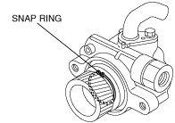
Gear Shaft Component Disassembly Note
1. Remove the snap ring to front body shown in the figure.
absggw00001881
|
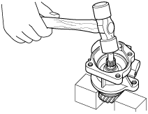
2. Tap the gear shaft from the shaft side using a plastic hammer to remove it.
absggw00001882
|
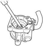
Oil Seal Disassembly Note
1. Tap the oil seal out using a flathead screwdriver.
absggw00001883
|
Oil Seal Assembly Note
1. Press fit the oil seal using a proper pipe.
absggw00001884
|
Gear Shaft Component Assembly Note
1. Set a proper pipe into the gear depression and press fit the gear shaft.
absggw00001885
|
2. Install the snap ring to front body shown in the figure.
absggw00001881
|
Side Plate Assembly Note
1. Install the side plate in the front pump body shown in the figure
absggw00001886
|
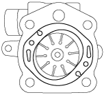
Rotor, Cam Ring, Vane, Assembly Note
1. Install the rotor in the front pump body shown in the figure.
2. Install the cam ring in the front pump body shown in the figure.
absggw00001887
|
3. Install the vane in the rotor.
Rear Pump Body Assembly Note
1. Install a new O-ring and the side plate to the front body.
2. Position the side plate using the rear pump body.
3. Install the rear body to the rear pump body.
absggw00001888
|
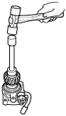
Stud Assembly Note
1. Tighten 2 nuts against each other on the stud, and then install it so that the stud projection is within the following specification.
absggw00001879
|