 |
dbg740zwb002
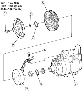
MAGNETIC CLUTCH DISASSEMBLY/ASSEMBLY
id074000800400
1. Disassemble in the order indicated in the table.
dbg740zwb002
|
|
1
|
Bolt
|
|
2
|
Pressure plate
|
|
3
|
Shim
|
|
4
|
Snap ring
|
|
5
|
A/C compressor pulley
|
|
6
|
Screw
|
|
7
|
Stator
(See Stator Removal Note.)
(See Stator Installation Note.)
|
|
8
|
Snap ring
|
|
9
|
A/C compressor body
|
2. Assemble in the reverse order of disassembly.
3. Adjust the magnetic clutch clearance. (See MAGNETIC CLUTCH ADJUSTMENT.)
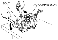
Bolt Removal/Installation Note
1. When removing or installing the bolt, hold the pressure plate in place as shown in the figure.
dbg740zwb006
|
2. When installing a new A/C compressor body, replace the recommended bolt.
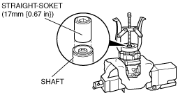
Stator Removal Note
1. Set a straight-socket (17 mm {0.67 in}) on the shaft of the A/C compressor to protect it.
2. Remove the stator using a pulley puller as shown in the figure.
dbg740zwb028
|
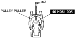
Stator Installation Note
1. Install the stator perpendicularly using the SST (49 H061 005) and a pulley puller as shown in the figure.
dbg740zwb029
|
Pressure Plate Installation Note
1. When installing the pressure plate, carry out magnetic clutch clearance adjustment.