DTC B1913, B1916, B1932, B1934
id080200801700
DTC
|
B1913
|
Driver-side air bag module system circuit short to ground
|
B1916
|
Driver-side air bag module system circuit short to power supply
|
|
B1932
|
Driver-side air bag module system resistance high
|
|
B1934
|
Driver-side air bag module system resistance low
|
|
DETECTION CONDITION
|
• resistance other than 1.5—3.7 ohms detected in driver‐side air bag module circuit
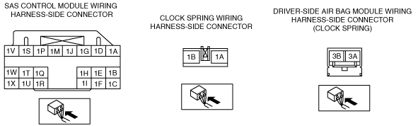
• Malfunction in wiring harness between driver-side air bag module and SAS control module
|
|
POSSIBLE CAUSE
|
• Open or short circuit in wiring harness between clock spring and SAS control module
• Clock spring malfunction
• Driver‐side air bag module malfunction
• SAS control module malfunction
|
|
![]() |
Diagnostic procedure
STEP |
INSPECTION |
ACTION |
|
---|---|---|---|
1
|
INSPECT DRIVER‐SIDE AIR BAG MODULE
• Using the M-MDS, verify the following PID/DATA monitor.
(See PID/DATA MONITOR TABLE.)
• Is the resistance of the driver-side air bag module normal?
|
Yes
|
Replace the SAS control module.
|
No
|
Go to the next step.
|
||
2
|
INSPECT DRIVER‐SIDE AIR BAG MODULE CONNECTOR (CLOCK SPRING)
• Turn the engine switch to LOCK position.
• Disconnect the negative battery cable and wait for 1 min or more.
• Remove the driver-side air bag module.
• Is there any malfunction of the driver-side air bag module connector?
|
Yes
|
Replace the air bag wiring harness and/or clock spring.
|
No
|
Go to the next step.
|
||
3
|
VERIFY WHETHER MALFUNCTION IS IN DRIVER‐SIDE AIR BAG MODULE OR RELATED WIRING HARNESS
• Connect the leads of SST (Fuel and thermometer checker) or apply 2-ohm resistance to driver-side air bag module connector terminals 3A and 3B.
• Set the resistance of SST (Fuel and thermometer checker) to 2-ohm position.
• Connect the negative battery cable.
• Turn the engine switch to ON position.
• Are DTCs B1913, B1916, B1932 and/or B1934?
|
Yes
|
Go to the next step.
|
No
|
Replace the driver-side air bag module.
|
||
4
|
INSPECT CLOCK SPRING
• Inspect the clock spring.
(See CLOCK SPRING INSPECTION.)
• Is the clock spring normal?
|
Yes
|
Go to the next step.
|
No
|
Replace the clock spring.
|
||
5
|
INSPECT WIRING HARNESS BETWEEN CLOCK SPRING AND SAS CONTROL MODULE
• Turn the engine switch to LOCK position.
• Disconnect the negative battery cable and wait for 1 min or more.
• Remove the column cover.
• Disconnect the clock spring connector.
• Remove the glove compartment.
• Disconnect the passenger‐side air bag module connector. (Vehicles with passenger-side air bag)
• Disconnect the driver and passenger‐side seat connectors. (Vehicles with side air bag)
• Disconnect the driver and passenger-side pre-tensioner seat belt connectors. (Vehicle with pre-tensioner seat belt)
• Remove the console.
• Disconnect the all SAS control module connectors.
• Inspect the wiring harness between SAS control module terminal 1S and clock spring terminal 1A, SAS control module terminal 1V and clock spring terminal 1B for the following:
• Is the wiring harness normal?
|
Yes
|
Go to the next step.
|
No
|
Replace the air bag wiring harness.
|
||
6
|
INSPECT AIR BAG SYSTEM WARNING LIGHT
• Connect the all SAS control module connectors.
• Connect the driver and passenger-side pre-tensioner seat belt connectors. (Vehicle with pre-tensioner seat belt)
• Connect the driver and passenger‐side seat connectors. (Vehicles with side air bag)
• Connect the passenger‐side air bag module connector. (Vehicles with passenger-side air bag)
• Connect the clock spring connector.
• Connect the negative battery cable.
• Turn the engine switch to ON position.
• Are DTCs B1913, B1916, B1932 and/or B1934?
|
Yes
|
Replace the SAS control module.
|
No
|
The system is normal at present. (Clear the malfunction from the memory.)
|