STEP
INSPECTION
ACTION
1
• Turn the ignition (F2, G6)/engine (WE-C, WL-3, WL-C, WLT-1, WLT-2) switch to the ON position.
• Verify that the fuel gauge needle does not move after ignition (F2, G6)/engine (WE-C, WL-3, WL-C, WLT-1, WLT-2) switch is turned off, or the display does not indicate F even though fuel tank is full.
• Is the fuel gauge normal?
Yes
Troubleshooting completed.
No
Go to the next step.
2
• Start the instrument cluster input/output check mode.
• Select the check code 22.
• Display value is 5—199?
Yes
Go to the next step.
No
Go to Step 4.
3
• Perform the check code 23 inspection.
• Is there any malfunction?
Yes
Replace the instrument cluster.
No
Go to the next step.
4
• Perform the check code 22 inspection.
• Is there any malfunction?
Yes
Go to the next step.
No
Go to Step 6.
5
• Turn the ignition (F2, G6)/engine (WE-C, WL-3, WL-C, WLT-1, WLT-2) switch off.
• Inspect the instrument cluster connector terminals for poor connection (such as damaged/pulled-out pins, and corrosion).
• Are the terminals normal?
Yes
Replace the instrument cluster.
No
Repair or replace the terminal.
6
• Turn the ignition (F2, G6)/engine (WE-C, WL-3, WL-C, WLT-1, WLT-2) switch to LOCK position.
• Remove the instrument cluster.
• Disconnect the instrument cluster connector.
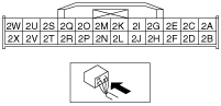
• Inspect for continuity between the following wiring harnesses.
-
― 2K terminal—GND
• Is there continuity?
Yes
Repair or replace the wiring harness between the instrument cluster and GND.
No
Go to the next step.
7
• Turn the ignition (F2, G6)/engine (WE-C, WL-3, WL-C, WLT-1, WLT-2) switch off.
• Inspect the fuel gauge sender unit connector terminals for poor connection (such as damaged/pulled-out pins, and corrosion).
• Are the terminals normal?
Yes
Go to the next step.
No
Repair or replace the terminal.
8
• Turn the ignition (F2, G6)/engine (WE-C, WL-3, WL-C, WLT-1, WLT-2) switch to LOCK position.
• Inspect for continuity following the wiring harness between instrument cluster and fuel gauge sender unit.
-
― 2K terminal—B terminal― 2I terminal—C terminal
• Is there continuity?
Yes
Go to the next step.
No
Repair or replace the wiring harness between the instrument cluster and the fuel gauge sender unit.
9
• Turn the ignition (F2, G6)/engine (WE-C, WL-3, WL-C, WLT-1, WLT-2) switch off.
• Is the fuel gauge sender unit installed properly?
Yes
Inspect the fuel gauge sender unit.
No
Reinstall the fuel gauge sender unit.