 |
dfc914zwc014
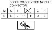
DOOR LOCK CONTROL MODULE INSPECTION
id091400807000
1. Remove the door lock control module without disconnecting the connector.
2. Measure the voltage at the door lock control module terminals as indicated below.
3. Disconnect the door lock control module connector before inspecting for continuity at terminals K, L, M, and N.
Terminal voltage list (Reference)
dfc914zwc014
|
|
Terminal |
Signal |
Connected to |
Test condition |
Voltage (V)/Continuity |
Action |
|---|---|---|---|---|---|
|
A
|
Power supply
|
D.LOCK 30 A fuse
|
Under any condition
|
B+
|
• Inspect D.LOCK 30 A fuse
• Inspect related harness
|
|
C
|
Unlock output
|
Door lock actuator
|
Door lock actuator is unlocked
|
0→B+→0
|
• Inspect door lock actuator
• Inspect related harness
|
|
Other
|
Below 1.0
|
||||
|
D
|
Lock output
|
Door lock actuator
|
Door lock actuator is locked
|
0→B+→0
|
• Inspect door lock actuator
• Inspect related harness
|
|
Other
|
Below 1.0
|
||||
|
F
|
Lock/Unlock input
|
Keyless control module
|
Transmitter lock button is pressed
|
B+→5→B+
|
• Inspect keyless control module
• Inspect transmitter
• Inspect related harness
|
|
Transmitter unlock button is pressed
|
B+→0→B+
|
||||
|
No transmitter unlock buttons are pressed
|
B+
|
||||
|
K
|
Lock input
|
Door lock-link switch
|
Driver’s side door is locked: inspect for continuity to ground
|
Yes
|
• Inspect door lock-link switch
• Inspect related harness
|
|
Driver’s side door is unlocked: inspect for continuity to ground
|
No
|
||||
|
L
|
Unlock input
|
Door lock-link switch
|
Driver’s side door is locked: inspect for continuity to ground
|
No
|
• Inspect door lock-link switch
• Inspect related harness
|
|
Driver’s side door is unlocked: inspect for continuity to ground
|
Yes
|
||||
|
M
|
System ground
|
GND
|
Under any condition: inspect for continuity to ground
|
Yes
|
• Inspect GND
|
|
N
|
Power ground
|
GND
|
Under any condition: inspect for continuity to ground
|
Yes
|
• Inspect GND
|