 |
absggw00001894
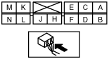
IMMOBILIZER UNIT INSPECTION
id091400823200
WE-C, WL-3, WL-C
1. Measure the voltage at the immobilizer unit terminals as indicated below.
2. Disconnect the immobilizer unit connector before inspecting for continuity at terminal C.
Terminal voltage table (reference)
absggw00001894
|
|
Terminal |
Signal |
Connected to |
Test condition |
Voltage (V)/continuity |
Action |
|---|---|---|---|---|---|
|
A
|
Communication with PCM
|
PCM
|
Engine switch at ON position
|
B+
|
• Inspect PCM
• Inspect related harness
|
|
Engine switch at LOCK position
|
Below 1.0
|
||||
|
C
|
GND
|
GND
|
Under any condition: inspect for continuity to ground
|
Yes
|
• Inspect GND
|
|
D
|
Power supply to coil
|
Coil
|
Key removed from key cylinder
|
Below 1.0
|
• Inspect coil
• Inspect related harness
|
|
Key inserted into key cylinder
|
Cannot be measured
|
||||
|
F
|
Key ID number input
|
Coil
|
Key removed from key cylinder
|
Below 1.0
|
• Inspect coil
• Inspect related harness
|
|
Key inserted into key cylinder
|
Cannot be measured
|
||||
|
H
|
Key reminder switch input
|
Key reminder switch
|
Key removed from key cylinder
|
Below 1.0
|
• Inspect key reminder switch
• Inspect related harness
|
|
Key inserted into key cylinder
|
B+
|
||||
|
J
|
Back‐up power supply
|
Battery
|
Under any condition
|
B+
|
• Inspect ROOM 10 A fuse
• Inspect related harness
|
|
K
|
Starter relay output
|
Starter relay
|
Engine switch at ON position
|
Below 1.0
|
• Inspect starter relay
• Inspect related harness
|
|
Engine switch at LOCK position
|
0
|
||||
|
L
|
Power supply
|
Engine switch
|
Engine switch at ON position
|
B+
|
• Inspect ENGINE 15 A fuse
• Inspect related harness
|
|
Engine switch at OFF position
|
Below 1.0
|
||||
|
M
|
Security light output
|
Security light
|
Security light neither illuminates nor blinks
|
B+
|
• Inspect security light
• Inspect related harness
|
WLT-2
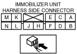
1. Measure the voltage at the immobilizer unit terminals as indicated below.
2. Disconnect the immobilizer unit connector before inspecting for continuity at terminal C.
Terminal voltage table (reference)
absggw00001959
|
|
Terminal |
Signal |
Connected to |
Test condition |
Voltage (V)/continuity |
Action |
|---|---|---|---|---|---|
|
A
|
Communication with DDS1
|
DDS1
|
Engine switch at ON position
|
B+
|
• Inspect DDS1
• Inspect related harness
|
|
Engine switch at LOCK position
|
Below 0.1
|
||||
|
B
|
—
|
—
|
—
|
—
|
—
|
|
C
|
GND
|
GND
|
Under any condition: inspect for continuity to ground
|
Yes
|
• Inspect GND
• Inspect related harness
|
|
D
|
Power supply to coil
|
Coil
|
Engine switch at LOCK position
|
Below 0.1
|
• Inspect coil
• Inspect related harness
|
|
Engine switch at ON position
|
Can not be measured
|
||||
|
E
|
—
|
—
|
—
|
—
|
—
|
|
F
|
Key ID number input
|
Coil
|
Engine switch at LOCK position
|
Below 0.1
|
• Inspect coil
• Inspect related harness
|
|
Engine switch at ON position
|
Can not be measured
|
||||
|
H
|
—
|
—
|
—
|
—
|
—
|
|
J
|
Back-up power supply
|
Battery
|
Under any condition
|
B+
|
• Inspect ROOM 10 A fuse
• Inspect related harness
|
|
K
|
—
|
—
|
—
|
—
|
—
|
|
L
|
Power supply
|
Engine switch
|
Engine switch at ON position
|
B+
|
• Inspect ENGINE 15 A fuse
• Inspect related harness
|
|
Engine switch at LOCK position
|
0
|
||||
|
M
|
Security light output
|
Security light
|
Security light neither illuminates nor blinks
|
B+
|
• Inspect security light
• Inspect related harness
|
|
N
|
—
|
—
|
—
|
—
|
—
|