 |
ecf918zw3n12
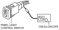
PANEL LIGHT CONTROL SWITCH INSPECTION
id091800806400
1. Connect the connector to the panel light control switch.
2. Connect the negative battery cable.
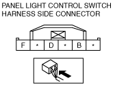
3. Measure the voltage at the panel light control switch using a tester.
4. If the value are not as specified in the Terminal Voltage List (Reference), inspect the parts under “Inspection item(s)” and related wiring harnesses.
5. If the system does not work properly even though the parts or related wiring harnesses do not have any malfunction, replace the panel light control switch.
Terminal Voltage Table (Reference)
ecf918zw3n12
|
|
Terminal |
Signal |
Connected to |
Test condition |
Voltage (V)/Continuity |
Inspection item(s) |
|
|---|---|---|---|---|---|---|
|
B
|
TNS
|
TNS relay
|
Headlight switch at TNS or headlight position
|
B+
|
• TAIL 10A fuse
• Related wiring harness
|
|
|
Other
|
1.0 or less
|
|||||
|
F
|
Ground
|
GND
|
Under any condition: inspect for continuity to ground
|
Continuity detected
|
• GND
• Related wiring harness
|
|
|
D
|
Illumination
|
Each illumination
|
Inspect using an oscilloscope (See Terminal D inspection.)
|
—
|
• Each illumination
• Related wiring harness
|
|
Terminal D inspection
1. Measure the wave pattern of the terminal D on the panel light control switch using an oscilloscope.
a6e8114w124
|
2. Set the headlight switch to either the TNS or headlight position.
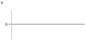
3. Set the panel light control switch to the brightest position.
4. Verify that the pattern on the screen is as shown in the figure.
a6e8114w125
|
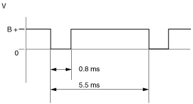
5. Verify that the pattern on the screen matches the pattern shown in the figure as the panel light control switch is gradually turned to the darkest position.
ecf918zw3n17
|