 |
a6e8112w154
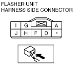
FLASHER UNIT INSPECTION
id091800851700
1. Connect the connector to the flasher unit.
2. Connect the negative battery cable.
3. Measure the voltage at the flasher unit using voltmeter.
4. If the value are not as specified in the Terminal Voltage List (Reference), inspect the parts under “Action” and related wiring harnesses.
5. If the system does not work properly even though the parts or related wiring harnesses do not have any malfunction, replace the flasher unit.
Terminal Voltage List (Reference)
a6e8112w154
|
|
Terminal |
Signal |
Connected to |
Test condition |
Voltage (V)/ Continuity |
Action |
|---|---|---|---|---|---|
|
A
|
Power supply
|
HAZARD 10 A fuse
|
Under any condition
|
B+
|
• Inspect HAZARD 10 A fuse
• Inspect related harness
|
|
D
|
Turn signal flasher (LH)
|
Turn signal light (LH)
|
Turn signal light (LH) flashes
|
Alternates
below 1.0 and B+
|
• Inspect turn signal light (LH)
• Inspect related harness
|
|
Hazard warning switch at on position
|
|||||
|
Other
|
Below 1.0
|
||||
|
F
|
Flasher unit ground
|
GND
|
Constant: inspect for continuity to ground
|
Yes
|
• Inspect GND
|
|
G
|
Turn signal flasher (RH)
|
Turn signal light (RH)
|
Turn signal light (RH) flashes
|
Alternates
below 1.0 and B+
|
• Inspect turn signal light (RH)
• Inspect related harness
|
|
Hazard warning switch at on position
|
|||||
|
Other
|
Below 1.0
|
||||
|
H
|
Hazard warning on
|
Hazard warning switch
|
Hazard warning switch at on position
|
Below 1.0
|
• Inspect hazard warning switch
• Inspect related harness
|
|
Hazard warning switch at off position
|
B+
|
||||
|
I
|
Turn switch on/off (RH)
|
Combination switch
|
Engine switch is at ON and turn switch (RH) on
|
B+
|
• Inspect combination switch
• Inspect related harness
|
|
Other
|
Below 1.0
|
||||
|
J
|
Turn switch on/off (LH)
|
Combination switch
|
Engine switch is at ON and turn switch (LH) on
|
B+
|
• Inspect combination switch
• Inspect related harness
|
|
Other
|
Below 1.0
|