 |
dcf920ztba09
ON-BOARD DIAGNOSTIC SYSTEM FUNCTION
id092000101800
Self-diagnostic Function
Malfunction detection function
Memory function
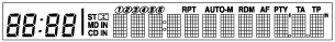
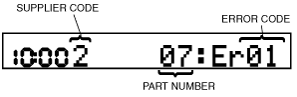
Display function
dcf920ztba09
|
|
Supplier code |
Supplier name |
|---|---|
|
1
|
SANYO Automedia
|
|
2
|
Panasonic
|
|
3
|
Clarion
|
|
4
|
Pioneer
|
|
Parts number |
Parts name |
|---|---|
|
03
|
CD player
|
|
05
|
CD changer (external)
|
|
06
|
CD changer (upper module)
|
|
07
|
MD player (lower module)
|
|
09
|
Base unit
|
|
10
|
MP3 applicable CD player
|
|
21
|
Center panel
|
|
22
|
MP3 applicable CD changer
|
|
Error code |
Malfunction description |
|---|---|
|
01
|
Internal mechanism error
|
|
02
|
Servo mechanism error
|
|
07
|
Disc reading error
|
|
08
|
Blank media
|
|
09
|
Unplayable files or tracks
|
|
10
|
BUS line (communication line) error
|
|
17
|
Incorrect combination
|
|
18
|
Incorrect combination
|
|
19
|
Communication line
|
|
20
|
Insufficient power supply
|
|
21
|
Amplifier related circuit
|
|
22
|
Tuner error
|
|
Screen display |
Malfunction location |
|
|---|---|---|
|
DTC |
Output signal |
|
|
03: Er01
|
—
|
CD player system
|
|
03: Er02
|
CHECK CD
|
CD player system
|
|
03: Er07
|
CHECK CD
|
CD player system
|
|
03: Er10
|
—
|
CD player communication circuit system
|
|
05: Er01
|
—
|
CD changer system
|
|
05: Er07
|
CHECK CD
|
CD changer system
|
|
05: Er10
|
—
|
CD changer communication circuit system
|
|
06: Er01
|
—
|
CD changer system
|
|
06: Er02
|
CHECK CD
|
CD changer system
|
|
06: Er07
|
CHECK CD
|
CD changer system
|
|
06: Er10
|
—
|
CD changer communication circuit system
|
|
07: Er01
|
—
|
MD player system
|
|
07: Er02
|
CHECK MD
|
MD player system
|
|
07: Er07
|
CHECK MD
|
MD player system
|
|
07: Er08
|
—
|
MD system
|
|
07: Er10
|
—
|
MD player communication circuit system
|
|
09: Er20
|
—
|
Power supply circuit to base unit
|
|
09: Er21
|
—
|
Base unit (peripheral circuit for power amplifier)
|
|
09: Er22
|
—
|
Base unit (peripheral circuit for tuner)
|
|
10: Er01
|
—
|
MP3 applicable CD player system
|
|
10: Er02
|
CHECK CD
|
MP3 applicable CD player system
|
|
10: Er07
|
CHECK CD
|
MP3 applicable CD player system
|
|
10: Er09
|
CHECK CD
|
MP3 applicable CD data
|
|
10: Er10
|
—
|
MP3 applicable CD player communication circuit system
|
|
21: Er17
|
—
|
Center panel system
|
|
21: Er18
|
—
|
Center panel system
|
|
21: Er19
|
—
|
Center panel system
|
|
22: Er01
|
—
|
CD system
|
|
22: Er02
|
—
|
CD system
|
|
22: Er07
|
—
|
CD system
|
|
22: Er09
|
CHECK CD
|
MP3 applicable CD data
|
|
22: Er10
|
—
|
MP3 applicable CD changer system
|
|
no Err
|
—
|
No DTCs stored
|
Diagnostic Assist Function
Information display
dcf902zwbs04
|
Speaker
1. Front speaker and tweeter (LH)
2. Front speaker and tweeter (RH)
3. Rear speaker*1 (LH)
4. Rear speaker*1 (RH)
Radio
e5u920zs5008
|
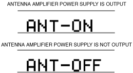
Antenna control condition
e5u920zs5202
|