 |
dcf922zwbo05
INSTRUMENT CLUSTER INSPECTION
id092200800400
Speedometer
Using the input/output check mode
1. Inspect the speedometer by setting it to check code 12 of the input/output check mode. (See INSTRUMENT CLUSTER INPUT/OUTPUT CHECK MODE.)
Using a speedometer tester
1. Adjust the tire pressure to the specification.
2. Using a speedometer tester, verify that the tester reading is as indicated in the table below.
|
Speedometer tester indication (km/h) |
Allowable range (km/h) |
|---|---|
|
20
|
19—21
|
|
40
|
39—41
|
|
60
|
58—62
|
|
80
|
78—82
|
|
100
|
98—102
|
|
120
|
118—122
|
|
140
|
137—143
|
3. Verify that the speedometer reading is within the range indicated in the table.
Tachometer
Using the input/output check mode
1. Inspect the tachometer by setting it to check code 13 of the input/output check mode. (See INSTRUMENT CLUSTER INPUT/OUTPUT CHECK MODE.)
Using M-MDS
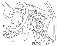
1. Connect the M-MDS to the DLC-2.
dcf922zwbo05
|
2. Compare the engine speed (M-MDS: RPM PID) with the tachometer indication.
Fuel gauge
1. Inspect the fuel gauge by setting it to check code 23 of the input/output check mode. (See INSTRUMENT CLUSTER INPUT/OUTPUT CHECK MODE.)
Water temperature gauge
1. Inspect the water temperature gauge by setting it to check code 25 of the input/output check mode. (See INSTRUMENT CLUSTER INPUT/OUTPUT CHECK MODE.)