1. Stereo camera safety information
1. Stereo camera learning
If the stereo camera is removed and installed, if the stereo camera is replaced, or if the front windshield glass is replaced, perform the stereo camera learning.
An indoor location is preferred when performing the stereo camera learning. Keep out of direct sunlight from the vehicle front and rear when performing at an outdoor location.
2. Stereo camera image blocking prohibited area
The stereo camera will not operate correctly if there are obstacles within the imaging range of the camera. Take care not to allow obstacles within the following range.
RHD
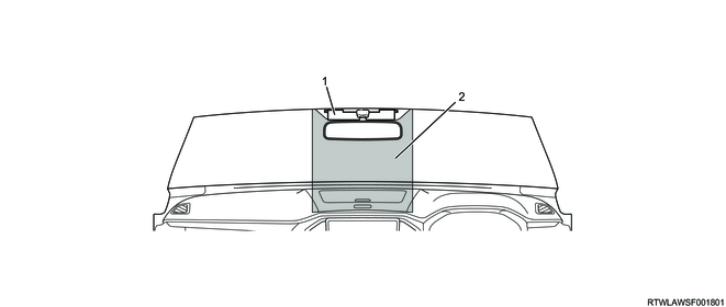
Legend
- Stereo camera
- Image blocking prohibited area
LHD
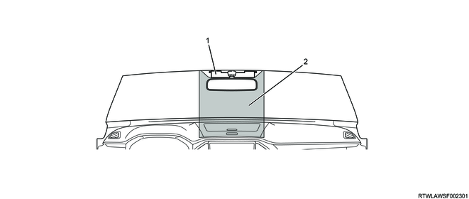
Legend
- Stereo camera
- Image blocking prohibited area
3. Film, sticker, and accessory component handling
1) Do not attach a film, sticker, or accessory component on the following places because the system may not work normally due to poor visibility of the stereo camera.
- Image blocking prohibited area
- Windshield
- Instrument panel
- Engine hood
4. Precautions for stereo camera learning
- There are no objects interrupting the view between the camera and the target.
- Perform the stereo camera learning with the vehicle unloaded.
- The tire air pressure is appropriate.
- The wheel alignment is appropriate.
- The front wheels are in the straight ahead position.
- There is no dirt, etc., on the windshield.
2. Stereo camera preparation
1) Referring to the diagram, set the target to a board, etc.
Note
- Set the target so that the target height line positions of both ends are the same at 1,200 mm {47.2 in}.
- Set the target on a board without uneven surface.
- When attaching the target with a tape, attach the tape to the margin of the target.
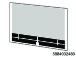
SST: 5-8840-3248-0 - target
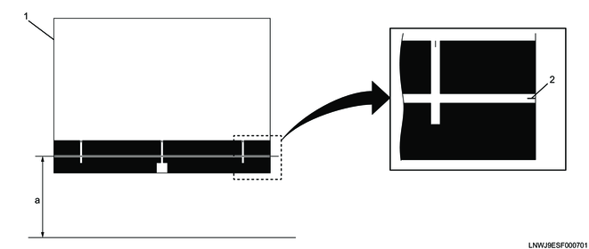
Legend
- Target
- Target height line
Dimensions
a: 1,200 mm { 47.2 in }
3. Stereo camera writing
1. Target setting
1) Stop the vehicle in a flat location.
2) Measure the distance between the right and left tires of the front and rear tires, and place mark A and B on the ground at the center position.
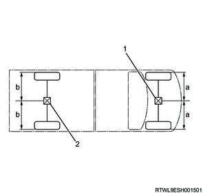
Legend
- Mark A
- Mark B
Legend
a. Distance from front tire end surface to center
b. Distance from rear tire end surface to center
3) Pass the string from mark B to mark A, and fix it at a position approximately 8,000 mm {315.0 in} from the front of the vehicle.
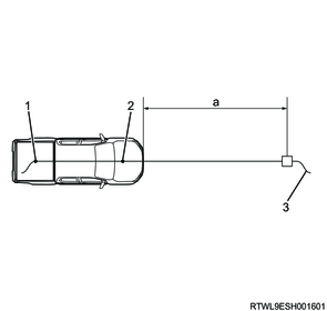
Legend
- Mark B
- Mark A
- String
Dimensions
a: 8,000 mm { 315.0 in }
4) Hang a plumb bob to the ground from the right and left front fender panels so that they pass through the center of the wheel, and then place mark C and D on the ground.
5) Place mark E and mark F at the position of 4,113 mm {161.9 in} from mark C and mark D, respectively.
Note
- Check that the distance from mark E to the vehicle center line is equal to that from mark F to the vehicle center.
6) Connect mark E and mark F with a straight line, and place mark G at the intersection of the string with the line.
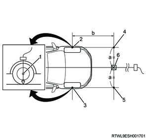
Legend
- Center of wheel
- Mark C
- Mark D
- Mark E
- Mark F
- Mark G
Legend
a. Distance from mark E or mark F to the vehicle center line
Dimensions
b: 4,113 mm { 161.9 in }
7) Hang a plumb bob to the ground from the center of the target, and set the target so that it matches with mark G.
Note
- Set the target so that it is parallel with the straight line between mark E and mark F.

Legend
- Target
- Target center line
- Mark G
2. Stereo camera learning
1) Connect the scan tool.
2) Select Special Function on the scan tool.
- Diagnostics > Body > Stereo Camera > Special Function
3) Select Camera Aiming, and follow the on-screen instructions to perform the stereo camera learning.
4) After completing the learning, verify the code displayed on the screen.
5) Referring to the following table, perform the work according to the code displayed on the screen.
| Code |
Procedure 1 |
Procedure 2 |
| 00 |
Because the learning is normally completed, turn OFF the ignition switch. |
- |
| 0D |
||
| FE |
| Code |
Procedure 1 |
Procedure 2 |
| 01 |
Inspect for the following, and if any abnormal conditions are found, resolve the cause or replace the related parts. ・Stereo camera installation position change ・Dirt on the stereo camera lens ・Object on the dashboard, object in front of or on the stereo camera ・Stickers, etc., on the windshield in front of the stereo camera lens ・Dirt on the windshield (inside/outside) ・Glass coating agent on the windshield ・Usage of a windshield other than the specified ・The vehicle slant ・Dirt or scratches on the target ・The distance between the target and the vehicle is the standard value. ・The target setting is parallel to the vehicle. ・Light unevenness on the target ・Direct light on the stereo camera |
1) Select "Special Function" on the scan tool. ・Diagnostics > Body > Stereo Camera > Special Function 2) Select Camera Aiming Clear, and follow the on-screen instructions to clear the learned value. 3) Select "Special Function" on the scan tool. ・Diagnostics > Body > Stereo Camera > Special Function 4) Select Camera Aiming, and follow the on-screen instructions to perform the stereo camera learning. 5) If the same error is detected after restarting the Camera Aiming, replace the stereo camera with a new one. |
| 02 |
||
| 03 |
||
| 04 |
||
| 05 |
||
| 06 |
||
| 07 |
||
| 08 |
||
| 0A |
||
| 0B |
||
| 0C |
||
| FD |
||
| 0E |
1) Select "Programming" on the scan tool. ・Diagnostics > Body > Stereo Camera > Programming 2) Select Download Vehicle Configuration Data, and follow the on-screen instructions to download the vehicle information. |
|
| 09 |
With the ignition switch ON, check that the distance from the front axle to the target is 4,113 mm {161.9 in}. |
<If there is no problem with the target setting position> 1) Select "Special Function" on the scan tool. ・Diagnostics > Body > Stereo Camera > Special Function 2) Select Restart Camera Aiming, and follow the on-screen instructions to perform the stereo camera learning. 3) If "Aiming Successful" is not displayed on the screen, restart the stereo camera learning procedure from the beginning. |
| <If there is a problem with the target setting position> 1) Correct the target setting position. 2) Select "Special Function" on the scan tool. ・Diagnostics > Body > Stereo Camera > Special Function 3) Select Camera Aiming Clear, and follow the on-screen instructions to clear the learned value. 4) Select "Special Function" on the scan tool. ・Diagnostics > Body > Stereo Camera > Special Function 5) Select Camera Aiming, and follow the on-screen instructions to perform the stereo camera learning. |
3. Stereo camera inspection
After completing the stereo camera learning, inspect whether the learning is performed correctly.
1) Place mark H and mark I at the position of 7,113 mm {280.0 in} from mark C or mark D, respectively.
Note
- Check that the distance from mark H to the vehicle center line is equal to that from mark I to the vehicle center.
2) Connect mark H and mark I with a straight line, and place mark J at the intersection of the string with the line.
3) Move the target placed on mark G to mark J.
Note
- Set the target so that it is parallel with the straight line between mark H and mark I
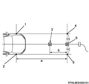
Legend
- Mark C
- Mark D
- Mark G
- Mark H
- Mark I
- Mark J
Legend
b. Move the target.
c. Distance from mark H or mark I to the vehicle center line
Dimensions
a: 7,113 mm { 280.0 in }
4) Connect the scan tool.
5) Turn ON the ignition switch.
6) Select Special Function on the scan tool.
- Diagnostics > Body > Stereo Camera > Special Function
7) Select Camera Inspection, and follow the on-screen instructions to perform the stereo camera inspection.
| Standard value |
|
| 7,800 to 8,200 mm { 307.1 to 322.8 in } |
Note
- The displayed value is the distance between the camera and the target detected by the camera.
- Perform the stereo camera learning again if the measured value is outside the standard value.
8) After completing the inspection, turn OFF the ignition switch.
9) Disconnect the scan tool.