1. Component views
Front hub and disc rotor (2WD (Except high ride suspension specifications))
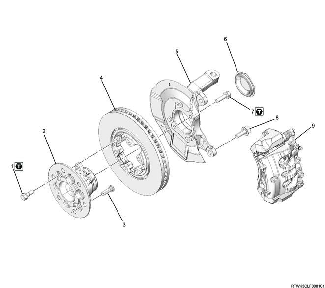
Part name
- Bolt
- Hub
- Wheel pin
- Brake disc
- Knuckle and dust cover
- Knuckle cap
- Bolt
- Bolt
- Brake caliper
Tightening torque
1: 93 to 113 N・m { 9.5 to 11.5 kgf・m / 69 to 83 lb・ft }
7: 85 N・m { 8.7 kgf・m / 63 lb・ft }
Front hub and disc rotor (2WD (High ride suspension specifications))
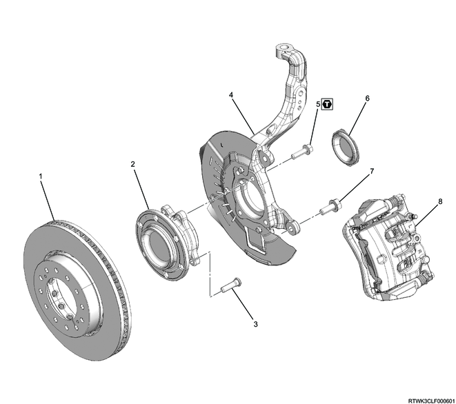
Part name
- Brake rotor
- Hub
- Wheel pin
- Knuckle and dust cover
- Bolt
- Knuckle cap
- Bolt
- Brake caliper
Tightening torque
5: 85 N・m { 8.7 kgf・m / 63 lb・ft }
Front hub and disc rotor (4WD)

Part name
- Brake disc
- Hub cap
- Cotter pin
- Lock nut
- Washer
- Hub
- Knuckle and dust cover
- Bolt
- Bolt
- Brake caliper
- Wheel pin
Tightening torque
4: 127 N・m { 13.0 kgf・m / 94 lb・ft }
8: 85 N・m { 8.7 kgf・m / 63 lb・ft }
2. Front hub disassembly
1. 2WD (Except high ride suspension specifications)
1) Place alignment marks on the front hub and brake rotor.
2) Secure the brake rotor using a vise and protective pad.
3) Remove the front hub from the brake rotor.
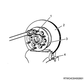
Legend
- Wheel pin
- Brake rotor
- Front hub
- Vise
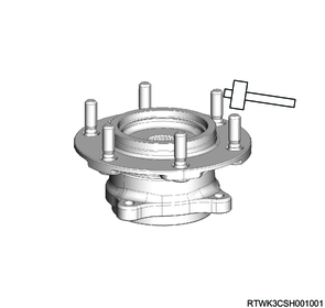
4) Remove the wheel pin from the front hub using a hammer.
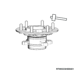
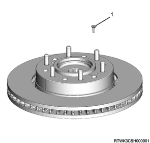
2. 2WD (High ride suspension specifications)
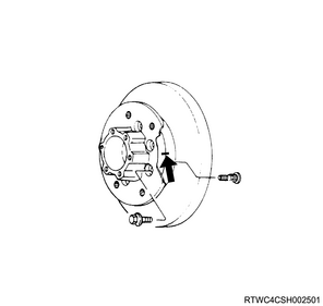
1) Remove the screw bolt from the brake rotor.
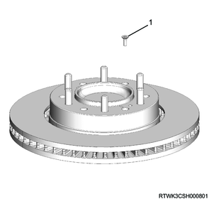
Legend
- Screw bolt
2) Remove the front hub from the brake rotor.
3) Remove the wheel pin from the front hub using a hammer.
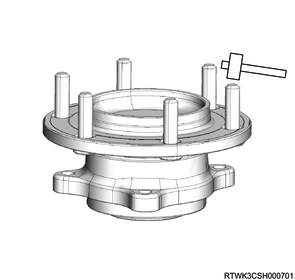
3. 4WD
1) Remove the screw bolt from the brake rotor.
Legend
- Screw bolt
2) Remove the front hub from the brake rotor.
3) Remove the wheel pin from the front hub using a hammer.