1. Component views
Camshaft
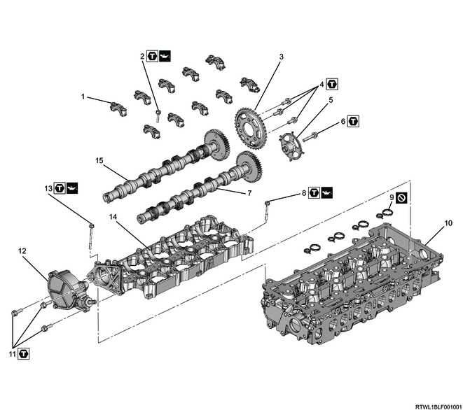
Part name
- Camshaft cap
- Bolt
- Camshaft sprocket
- Bolt
- Cam angle sensor rotor
- Bolt
- Inlet camshaft
- Bolt
- Gasket
- Cylinder head
- Bolt
- Vacuum pump
- Bolt
- Camshaft carrier
- Exhaust camshaft
Tightening torque
2: 7.0 N・m { 0.7 kgf・m / 62 lb・in }
4: 25 N・m { 2.5 kgf・m / 18 lb・ft }
6: 25 N・m { 2.5 kgf・m / 18 lb・ft }
8: 7.0 N・m { 0.7 kgf・m / 62 lb・in }
11: 25 N・m { 2.5 kgf・m / 18 lb・ft }
13: 7.0 N・m { 0.7 kgf・m / 62 lb・in }
2. Cylinder head cover removal
3. Camshaft carrier removal
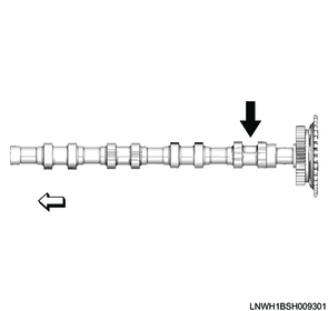
1) Remove the cam angle sensor rotor from the inlet camshaft.
Note
- Referring to the diagram, secure the section indicated by the arrow.
Fixing position
2) Turn the crankshaft in the forward direction (clockwise) to align the inlet camshaft and the exhaust camshaft notches to the camshaft cap alignment marks.
Caution
- Do not rotate the crankshaft until the camshaft carrier is reinstalled.
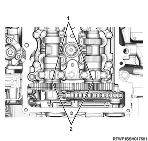
Legend
- Alignment mark
- Notch
3) Place the paint marking to the timing chain and camshaft sprocket.

Legend
- Camshaft sprocket
- Timing chain
- Paint marking
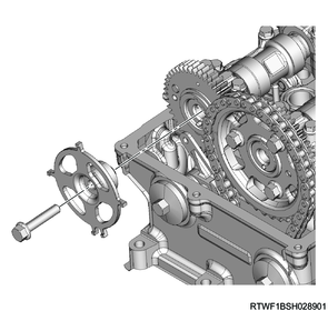
4) Remove the timing chain tensioner and gasket from the flywheel housing.
Caution
- Do not reuse the gasket.
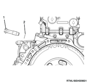
Legend
- Timing chain tensioner
- Gasket
5) Remove the timing chain from the camshaft sprocket.
6) Disconnect the vacuum hose from the vacuum pump.
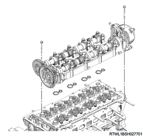
7) Remove the camshaft carrier and gasket from the cylinder head.
Caution
- Do not reuse the gasket.
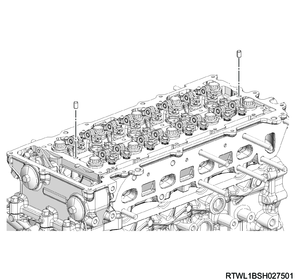
8) Remove the dowel pin from the cylinder head.
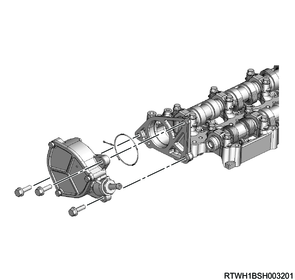
4. Vacuum pump removal
1) Remove the vacuum pump from the camshaft carrier.
Caution
- Seal the pipes, hoses, and ports to prevent the intrusion of foreign material.
5. Camshaft removal
1) Measure the axial direction clearance of the camshaft gear and camshaft cap using a feeler gauge.
Note
- If the measured value exceeds the limit, replace the camshaft.
Standard: 0.050 to 0.130 mm { 0.0020 to 0.0051 in }
Limit: 0.250 mm { 0.0098 in }
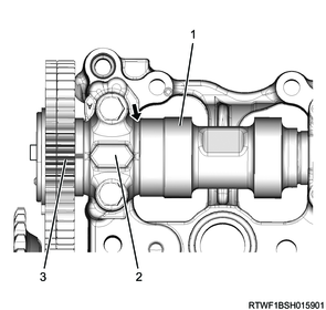
Legend
- Camshaft
- Camshaft cap
- Camshaft gear
2) Use the M5 lock bolt to secure the inlet camshaft gear.

Legend
- M5 bolt
3) Remove the camshaft cap from the camshaft carrier.
Note
- Check that there are installation position markings on the camshaft caps.

4) Remove the inlet camshaft and exhaust camshaft from the camshaft carrier.
Caution
- Take measures to prevent the inlet and exhaust sides from becoming mixed up.

Legend
- Camshaft cap
- Inlet camshaft
- Exhaust camshaft
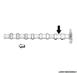
5) Remove the camshaft sprocket from the exhaust camshaft.
Note
- Referring to the diagram, secure the section indicated by the arrow.
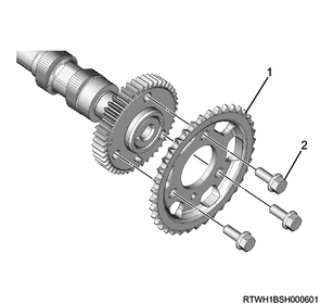
Legend
- Camshaft sprocket
- M8 bolt
Fixing position