1. Component views
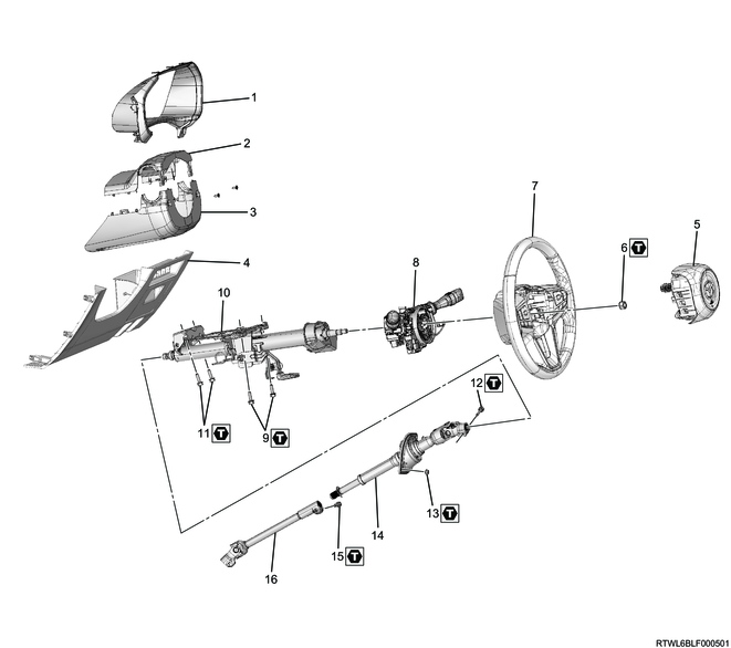
Steering column
Part name
- Meter cluster
- Steering cowl upper
- Steering cowl lower
- Instrument panel driver-side lower cover
- Driver airbag
- Nut
- Steering wheel
- Combination switch and SRS coil
- Bolt
- Steering column
- Bolt
- Bolt
- Nut
- Second steering shaft
- Bolt
- Lower second steering shaft
Tightening torque
6: 35 N・m { 3.6 kgf・m / 26 lb・ft }
9: 20 N・m { 2 kgf・m / 15 lb・ft }
11: 20 N・m { 2.0 kgf・m / 15 lb・ft }
12: 31 N・m { 3.2 kgf・m / 23 lb・ft }
13: 6.5 N・m { 0.7 kgf・m / 58 lb・in }
15: 31 N・m { 3.2 kgf・m / 23 lb・ft }
2. SRS airbag safety information
1. Handling deployed airbag
Warning
- When handling the airbag, the safety precautions must be observed.
- The surface of the deployed airbag may contain a small amount of sodium hydroxide.
This is a byproduct of the deployment reaction, and may cause irritation if it comes in contact with the skin or eyes. - Be sure to wear gloves and safety glasses when handling an airbag after deployment.
- Wash hands with soap after handling.
Caution
- After the airbag is deployed, inspect for burning or melting caused by excessive heat, or any other problems.
- If the SRS coil is damaged, replace it.
2. Handling undeployed airbag assembly
Warning
- When transporting an undeployed airbag, make sure that the trim cover is facing away from your body.
- Never carry an airbag with pretensioner by holding the connector or harness.
- When placing an undeployed airbag, make sure to face the trim cover upward.
- Do not put any object on the steering wheel with the airbag surface facing downward.
- Not following this procedure may result in fire or injuries.
3. SRS airbag preparation
1. SRS deactivation
1) Set the ignition switch to LOCK and remove the key.
Note
- For models with the passive entry and start system, turn the power mode OFF.
2) Remove the SRS fuse from the fuse relay box.
3) Disconnect the battery cable from the battery negative terminal.
Caution
- After turning OFF the ignition switch (power mode for models with passive entry and start system), do not disconnect the battery cable within 3 minutes.
- If the battery cable is disconnected within 3 minutes, the vehicle electronic control system may malfunction.
- If the battery cable is disconnected, perform the setting of the front door power window switch with AUTO UP/AUTO DOWN function after connecting the battery negative terminal.
- After disconnecting the battery cable, do not perform work for approximately 15 seconds.
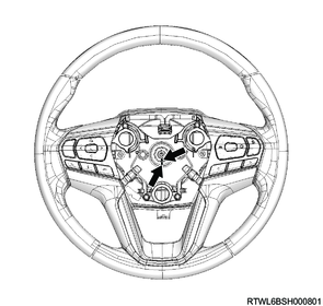
4. Driver airbag removal
1) Insert a hexagonal wrench or precision screwdriver into the holes on both sides of the steering wheel cover.
Note
- Push the wire in the direction of the arrow until the driver airbag is removed.

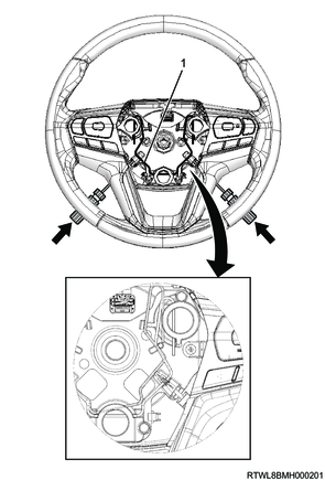
Legend
- Wire
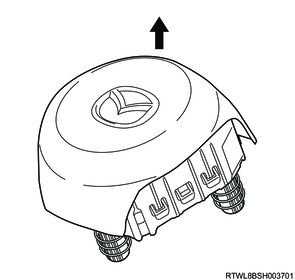
2) Remove the driver airbag from the steering wheel.
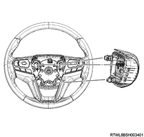
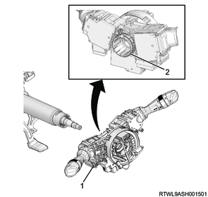
3) Disconnect the airbag connector from the driver airbag.
4) Disconnect the horn connector from the driver airbag.

Legend
- Airbag connector
- Horn connector
Warning
- When transporting an airbag, keep it away from your body.
- When placing an undeployed airbag, make sure to face the trim cover upward and place it on a flat surface.
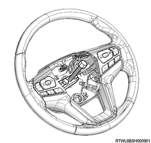
5. Steering wheel removal
1) Put the tires in a forward travel position.
2) Draw alignment marks on the steering wheel and steering shaft.
3) Remove the nut from the steering shaft.
4) Remove the steering wheel from the steering shaft using the special tool.
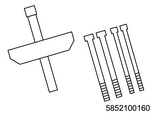
SST: 5-8521-0016-0 - steering wheel remover
Caution
- The steering wheel should never be removed using a hammer or tool that causes shock.
The steering wheel is designed to absorb impact.
6. Knee air bag removal
1. Models with knee airbags
Refer to "8.Restraints 8B.Airbag Systems knee air bag removal".
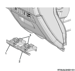
7. Instrument panel driver-side lower cover removal
1. Models without knee airbags
1) Disconnect the wire from each lever.
2) Remove the hood lock control lever and fuel filler lid opener lever from the instrument panel driver-side lower cover.
Note
- Press the claw section and pull out each lever.
RHD
Legend
- Hood lock control lever
- Fuel filler lid opener lever
- Claw section
LHD
Legend
- Fuel filler lid opener lever
- Hood lock control lever
- Claw section
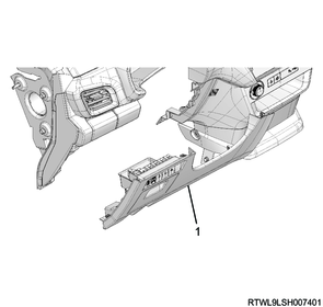
3) Remove the instrument panel driver-side lower cover from the instrument panel.
RHD

Legend
- Instrument panel driver-side lower cover
LHD
Legend
- Instrument panel driver-side lower cover
4) Remove the connector from the instrument panel driver-side lower cover.
8. Steering cowl removal
1) Remove the steering cowl from the steering shaft.
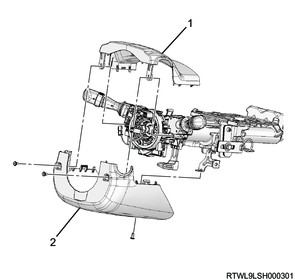
Legend
- Steering upper cowl
- Steering lower cowl
9. Combination switch removal
Caution
- Because the combination switch is integrated with the SRS coil, do not remove it or rotate the combination switch.
Set the front wheels in the straight ahead position before performing work.
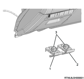
1) Check that the neutral marking of the combination switch aligns when the front wheels are set in the straight ahead position.
2) Hold the metal band ends to open the metal band.
3) Keeping the metal band open, remove the combination switch from the steering shaft.
Legend
- Combination switch
- Metal band
4) Disconnect the connector from the combination switch.
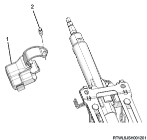
10. Steering lock removal
1) Remove the shear bolt (whose head is twisted off after tightening) using an extractor, reverse tap, etc.
2) Remove the steering lock from the steering shaft.
Models without the passive entry and start system

Legend
- Steering lock
- Shear bolt
- ICU antenna coil portion
Models with the passive entry and start system
Legend
- Steering lock
- Shear bolt
11. Steering shaft removal
1) Place alignment marks on the steering column.
Caution
- Do not place the alignment marks on the plastic portion.
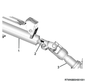
Legend
- Steering column
- Alignment mark
- Second steering shaft
2) Place alignment marks on the lower second steering shaft.
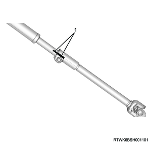
Legend
- Alignment mark
3) Place alignment marks on the universal joint of the lower second steering shaft.
4) Disconnect the universal joint of the lower second steering shaft from the power steering unit.
5) Lock the tilt lever.
6) Remove the lower second steering shaft from the second steering shaft.
Note
- Disconnect the lower second steering shaft at the position shown in the diagram.
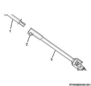
Legend
- Second steering shaft
- Remove the bolt.
- Lower second steering shaft
12. Steering column removal
1) Disconnect the harness connector from the steering column.
Note
- Disconnect the ignition switch harness connector on the lower side of the steering column.
2) Remove the dust cover from the vehicle.
3) Remove the steering column from vehicle.
4) Place alignment marks on the universal joint of the second steering shaft.
5) Remove the second steering shaft from the steering column.
Caution
- Do not release the tilt lever lock with the steering column removed.