1. Engine harness inspection
1) Disconnect the engine harness from the TCM.
2) Check for continuity between each connector terminal combinations listed in the table using a DMM.
Note
- Check that continuity is as specified in the table.
- A resistance value of 100 kΩ or more may be detected when resistance is measured between the terminals, but this is not a malfunction.
Caution
- Do not damage the terminals.
| Terminal name |
Continuity |
| SP+ - SP- |
Yes |
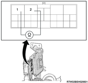
Legend
- SP+
- SP-
2. Output speed sensor inspection
1) Remove the output speed sensor from the transmission.
2) Check for continuity between each connector terminal combinations listed in the table using a DMM.
Note
- Check that continuity is as specified in the table.
- A resistance value of 100 kΩ or more may be detected when resistance is measured between the terminals, but this is not a malfunction.
Caution
- Do not apply impact to the output speed sensor.
- Do not damage the terminals.
| Terminal name |
Continuity |
| SP+ - SP- |
Yes |

Legend
- SP+
- SP-
3) Connect the battery positive terminal the SP+ terminal and the battery negative terminal to the SP- terminal via a 100 Ω resistor and ammeter.
Caution
- Do not apply impact to the output speed sensor.
- Do not damage the terminals.
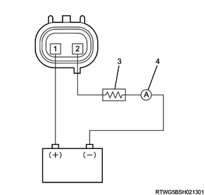
Legend
- SP+
- SP-
- 100 Ω resistor
- Ammeter
4) Inspect the current of the steel material (non-magnetic) while brushing to the left and right with the tip of the input speed sensor (within 5 mm {0.197 in}).
Caution
- Do not hit or damage the steel material with the input speed sensor when inspecting the current.
- Do not damage the terminals.
| Signal |
Current |
| High |
12.0 to 16.0 mA |
| Low |
4.0 to 8.0 mA |
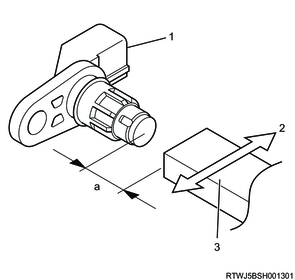
Legend
- Output speed sensor
- Shaking direction
- Steel material
Standard value
a. 5 mm {0.197 in} or less