1. Introduction to the trouble diagnosis of brake
Note
- The scan tool DTC display shows an alphabetic character + 4 digits + 2 digits, such as DTC C0020[01].
- The final 2 digits of FTB show additional information on problems.
1. About self-diagnosis
The EHCU has a self-diagnosis function and performs the initial check when the system is started to determine the presence of system malfunctions and failed sections. If a malfunction is found, it illuminates the ABS, brake system, and ESC warning lights to notify of the malfunction and stores the DTC.
The illuminated warning light is turned OFF each time the ignition switch is turned OFF, but the DTC will continue to be stored until cleared.
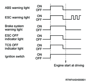
2. Trouble diagnosis based on illumination pattern
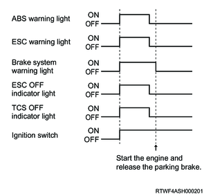
If a malfunction is found in the warning light illumination pattern inspection when the ignition switch is turned ON, or if a warning light illuminates during a test drive, perform the trouble diagnosis indicated in the following chart for that particular illumination pattern.
Test drive after completion of repair
After the repair, temporarily turn the ignition switch OFF and then restart the engine to verify that each light turns OFF.
1) All lights illuminate normally.
Normal
2) One of the lights does not illuminate.
Light control circuit failure
Refer to "54.Brake Control 4A.Troubleshooting(ABS/ESC) ABS warning light illuminating circuit system check".

3) The warning light remains illuminated.
Observe the DTC information.
If a DTC is stored, perform trouble diagnosis according to the diagnostic procedure for each DTC. If no DTC is stored, inspect the warning light control circuit.
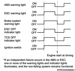
4) The warning light illuminates when the vehicle is running.
A DTC is stored. Observe the DTC information, and perform trouble diagnosis according to the diagnostic procedure for each DTC.
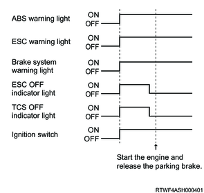
5) ESC OFF indicator light remains illuminated.
ESC OFF switch circuit failure When the ESC operation is inhibited with the ESC OFF switch, the ESC OFF indicator light illuminates. It always enters the operation standby state when the engine is started.
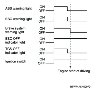
6) The ESC warning light flashes while driving.
It is normal when displayed during ESC operation.
2. Diagnostic trouble codes (DTCs)
Every time the ignition switch is turned ON, the control unit performs an initial check on most of the wiring and components, records any detected system failures in the control unit memory, and performs a fail-safe control depending on the DTC. Also, if a failure occurs in the system, the warning light in the instrument panel cluster illuminates to notify the driver.
1. DTC display method
Current and past DTCs stored in the EHCU can be observed on the scan tool.
2. DTC clearing method
A DTC cannot be cleared without using a scan tool.
3. Performing diagnosis
1. During general maintenance
Make sure to follow the following precautions when maintaining or diagnosing the ABS/ESC and other vehicle control systems.
- When welding the vehicle using an electric arc welder, remove the EHCU connector before welding.
- When installing or removing the EHCU connector, do so with the ignition switch OFF.
- Do not disassemble the EHCU.
- Take sufficient care to prevent foreign material from entering the hydraulic pressure circuit when inspecting or maintaining the brakes.
- The DTC is set if only the rear wheels are rotated using a drum tester or with the vehicle jacked up. Therefore, clear the DTC after work.
2. Computer system maintenance
Be careful not to apply overcurrent to the EHCU circuit. When inspecting for open circuits or short circuits, do not ground the circuit or apply voltage to it without careful consideration. Only inspect these circuits using a circuit tester with high internal resistance or using the special tools mentioned in this section. When the ignition switch is in the ON position, do not connect or disconnect the power supply to/from the EHCU. Make sure to place the ignition switch in the OFF position before disconnecting or connecting the battery cable, fuse, or connector.
Caution
- As the CAN communication line is disconnected if the ignition switch is turned ON with the harness removed from the EHCU, clear the DTCs in the systems performing CAN communication after work.
- Do not run the vehicle with the EHCU removed.
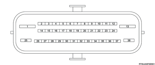
3. Inspection between EHCU terminals
EHCU terminal layout
| Circuit inspected |
Measurement terminal |
Ignition switch |
Measurement range |
Standard value |
Remarks |
|
| + |
- |
|||||
| Disconnect the connectors to measure each terminal. |
||||||
| EHCU power supply |
1 |
38 |
OFF |
DCV |
10 to 16 V |
- |
| 25 |
38 |
OFF |
DCV |
10 to 16 V |
- |
|
| 28 |
38 |
OFF |
DCV |
0 V |
- |
|
| 28 |
38 |
ON |
DCV |
10 to 16 V |
- |
|
| EHCU ground |
13 |
Ground |
OFF |
Ω |
0 to 1 Ω |
- |
| 38 |
Ground |
OFF |
Ω |
0 to 1 Ω |
- |
|
| Hill descent control switch (Models equipped with ESC) |
9 |
38 |
OFF |
Ω |
∞ Ω |
Release the hill descent control switch. |
| 9 |
38 |
OFF |
Ω |
0 to 1 Ω |
Depress the hill descent control switch. |
|
| ESC OFF switch (Models equipped with ESC) |
15 |
38 |
OFF |
Ω |
∞ Ω |
Release the ESC OFF switch. |
| 15 |
38 |
OFF |
Ω |
0 to 1 Ω |
Depress the ESC OFF switch. |
|
4. When replacing the EHCU
The EHCU itself rarely malfunctions. Therefore, when replacing the EHCU, inspect the connection status of the connectors in advance. In addition, inspect for short circuits between wire harnesses.
5. Intermittent trouble
Because intermittent trouble often occurs due to temporary connection failures of wire harnesses and connectors, shake the wire harnesses without damaging them, then inspect them.