1. Component views
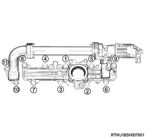
Timing chain
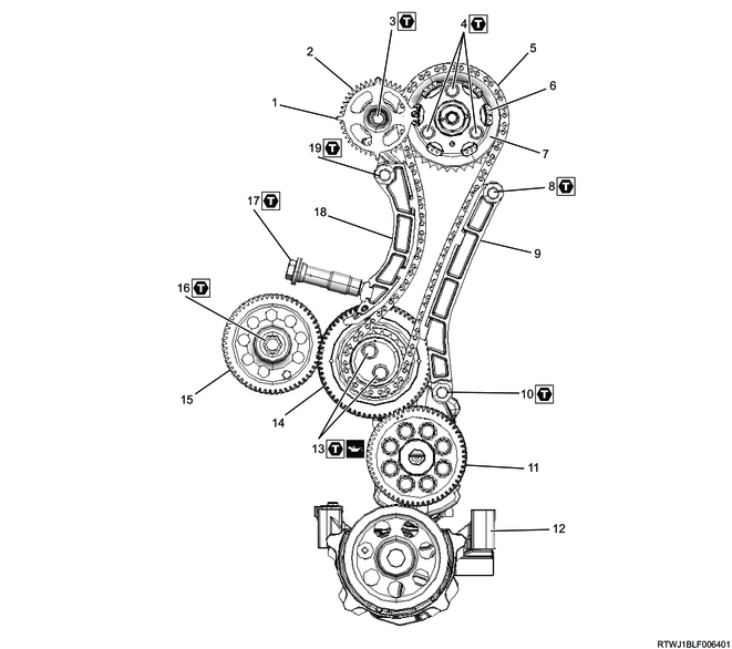
Part name
- Cam angle sensor rotor
- Inlet camshaft gear
- Bolt
- Bolt
- Timing chain
- Exhaust camshaft gear
- Camshaft sprocket
- Bolt
- Timing chain guide
- Bolt
- Crank gear
- Oil pump
- Bolt
- Idle gear A
- Supply pump gear
- Nut
- Timing chain tensioner
- Timing chain tension lever
- Bolt
Tightening torque
3: 25 N・m { 2.5 kgf・m / 18 lb・ft }
4: 25 N・m { 2.5 kgf・m / 18 lb・ft }
8: 25 N・m { 2.5 kgf・m / 18 lb・ft }
10: 25 N・m { 2.5 kgf・m / 18 lb・ft }
13: 32 N・m { 3.3 kgf・m / 24 lb・ft }
16: 64 N・m { 6.5 kgf・m / 47 lb・ft }
17: 70 N・m { 7.1 kgf・m / 52 lb・ft }
19: 25 N・m { 2.5 kgf・m / 18 lb・ft }
2. Flywheel housing installation
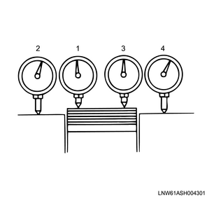
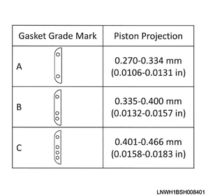
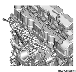
Measure the protrusion amount of the piston head in order to select the gasket grade.
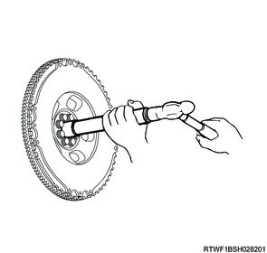
1) Measure the protrusion amount of the piston head using a dial gauge.
Caution
- The measurement point should be as close to the cylinder block as possible.
- The difference between the protruding amount of each piston must be within the specified range.
Standard: 0.05 mm { 0.0020 in }


Legend
- Measurement point
- Measurement point
- Measurement point
- Measurement point
Legend
- Measurement point
- Measurement point
- Measurement point
- Measurement point
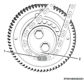
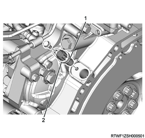
2) Turn the crankshaft in the forward direction (clockwise) to align the idle gear A alignment mark.
Note
- Align the alignment marks at the same time at the two locations: the alignment mark of idle gear A and the crank gear, the alignment mark of idle gear A and the supply pump gear.
Caution
- After the alignment marks are aligned, do not rotate the crankshaft until the camshaft carrier is installed.
Crank gear side alignment mark
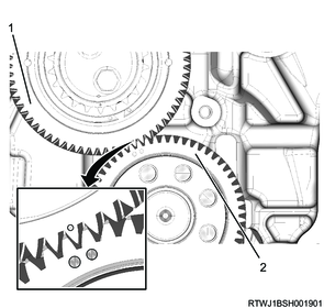
Legend
- Idle gear A
- Crank gear
Supply pump gear side alignment mark
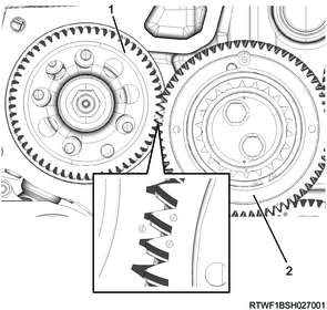
Legend
- Supply pump gear
- Idle gear A
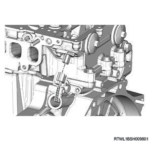
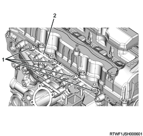
3) Install the timing chain to the idle gear A sprocket.
Note
- Align the timing chain yellow paint section with the flange timing mark, and install.
- Check whether the idle gear A sprocket white paint teeth section and flange timing mark are aligned.
Legend
- Timing chain yellow paint section
- Flange timing mark
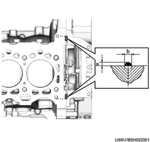
4) Apply ThreeBond 1207B or equivalent to the position on the flywheel housing shown in the diagram.
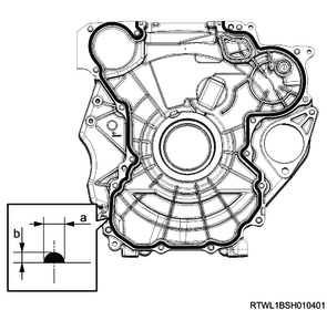
Standard value
a: 4.0 to 5.0 mm { 0.157 to 0.197 in } Bead width
b: 2.0 to 3.0 mm { 0.079 to 0.118 in } Bead height
5) Apply ThreeBond 1207B or equivalent to the positions on the cylinder block and crankcase shown in the diagram.

Standard value
a: 4.0 to 5.0 mm { 0.157 to 0.197 in } Bead width
b: 2.0 to 3.0 mm { 0.079 to 0.118 in } Bead height
6) Install the flywheel housing to the cylinder block in the order shown in the diagram.
Caution
- Carefully wipe away any gasket that has leaked out from between the aligning surfaces of the flywheel housing and cylinder block.
Tightening torque: 52 N・m { 5.3 kgf・m / 38 lb・ft }

3. Crankshaft rear oil seal installation
1) Install the crankshaft rear oil seal and slinger to the crankshaft using the special tool.
Caution
- Do not reuse the crankshaft rear oil seal.
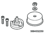
SST: 5-8840-3225-0 - oil seal installer
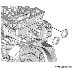
2) Check the dimension of the crankshaft end face and the crankshaft rear oil seal end face.
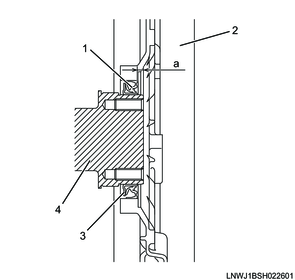
Legend
- Crankshaft rear oil seal
- Flywheel housing
- Crankshaft rear slinger
- Crankshaft
Standard value
a: 2.7 to 3.3 mm { 0.106 to 0.130 in }
4. Flywheel installation
1. Manual transmission models
1) Apply engine oil to the threaded portions and seating surfaces of the bolts.
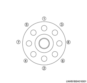
2) Temporarily tighten the washer and flywheel to the crankshaft in the order shown in the diagram.
Note
- Verify that the washer does not rotate on the flywheel.
Legend
- Flywheel
- Washer
- Bolt
Caution
- Do not damage the flywheel sensor rotor section.
3) Install the special tool to the starter motor installation section of the flywheel housing.
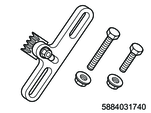
SST: 5-8840-3174-0 - crankshaft stopper
4) Final tighten the flywheel to the crankshaft in the order shown in the diagram.
Tightening torque: 40 N・m { 4.1 kgf・m / 30 lb・ft } 1st time
Tightening Angle : 60 to 90 ° 2nd time
5) Remove the special tool from the starter motor installation section of the flywheel housing.
6) Place the pilot bearing so that it crosses the crankshaft bearing installation hole perpendicularly.
7) Install the pilot bearing to the flywheel using the special tool.
Note
- Drive in the pilot bearing outer race using a hammer.
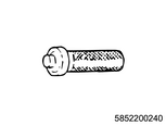
SST: 5-8522-0024-0 - pilot bearing installer
2. Automatic transmission models
1) Apply engine oil to the threaded portions and seating surfaces of the bolts.
2) Temporarily tighten the following parts to the crankshaft in the order shown in the diagram.
- Washer
- Flexible plate
- Flywheel
Caution
- Do not damage the flywheel sensor rotor section.
3) Install the special tool to the starter motor installation section of the flywheel housing.
SST: 5-8840-3174-0 - crankshaft stopper
4) Final tighten the flywheel to the crankshaft in the order shown in the diagram.
Tightening torque: 40 N・m { 4.1 kgf・m / 30 lb・ft } 1st time
Tightening Angle : 120 ° 2nd time
Tightening Angle : 30 to 60 ° 3rd time
Caution
- The total rotation angle should be 150 to 180°.
5) Remove the special tool from the starter motor installation section of the flywheel housing.
5. CKP sensor installation
1) Apply soapy water to the O-ring.
2) Install the CKP sensor to the flywheel housing.
Tightening torque: 5.0 N・m { 0.51 kgf・m / 44.3 lb・in }
Legend
- O-ring
- CKP sensor
3) Connect the connector to the CKP sensor.
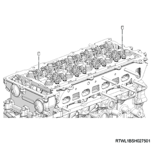
6. Cylinder head installation
1) Clean the upper surface of the cylinder block and lower surface of the cylinder head using a scraper.
Caution
- Do this carefully so as to not damage the upper surface of the cylinder block or lower surface of the cylinder head.
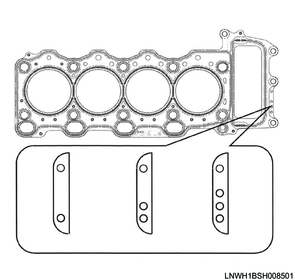
2) Select the cylinder head gasket grade based on the average piston head protrusion amount.
Caution
- Do not reuse the cylinder head gasket.
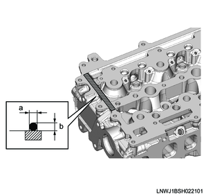
3) Apply ThreeBond 1207B or equivalent to the positions on the cylinder block shown in the diagram.
Caution
- After applying the liquid gasket, install the cylinder head within 5 minutes.
Standard value
a: 2.0 to 3.0 mm { 0.079 to 0.118 in } Bead height
b: 3.0 to 4.0 mm { 0.118 to 0.157 in } Bead width
4) Place the cylinder head gasket on the cylinder block.
Caution
- Do not reuse the cylinder head gasket.
5) Align the dowel positions, and place the cylinder head on the cylinder block.
Caution
- Do not damage the cylinder head gasket.
6) Apply engine oil to the following locations.
- Cylinder head mounting bolt threaded portion
- Cylinder head mounting bolt seating surface
- Washer
7) Tighten the cylinder head bolts to the cylinder head using the special tool and a torque wrench in the order shown in the diagram.
Caution
- Do not reuse the cylinder head bolts.
SST: 5-8840-0266-0 - angle gauge
Tightening torque: 115 N・m { 11.7 kgf・m / 85 lb・ft } 1st time
Tightening torque: 115 N・m { 11.7 kgf・m / 85 lb・ft } 2nd time
Note
- Retighten to the same torque to prevent variations in the tightening torque.
Tightening Angle : 90 to 120 ° 3rd time
Tightening Angle : 90 to 120 ° 4th time

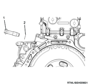
8) Install the bolts to the flywheel housing in the order shown in the diagram.
Tightening torque: 25 N・m { 2.5 kgf・m / 18 lb・ft }

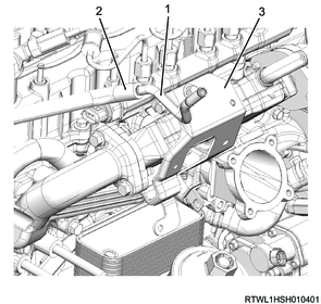
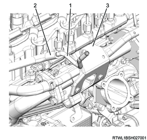
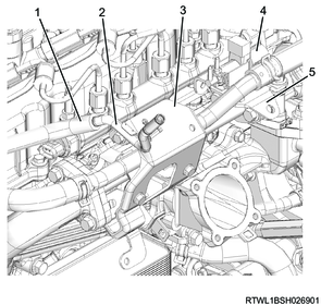
9) Install the following parts to the cylinder head.
- Timing chain tension lever
- Timing chain guide bolt
- Timing chain lever pivot
Tightening torque: 25 N・m { 2.5 kgf・m / 18 lb・ft }

Legend
- Timing chain tension lever
- Timing chain guide bolt
- Timing chain lever pivot
10) Apply LOCTITE 262 to the threaded portion of the plug.
11) Install the plug to the cylinder head.
Tightening torque: 25 N・m { 2.5 kgf・m / 18 lb・ft }
12) Connect the connector to the CMP sensor.
7. Camshaft carrier installation
1) Install the dowel pin to the cylinder head.
Note
- Insert until full contact is made.
2) Check that the inlet camshaft and the exhaust camshaft notches are aligned with the camshaft cap alignment marks.

Legend
- Alignment mark
- Notch
3) Confirm that the 4 gaskets are installed to the lower surface of the camshaft carrier.
4) Referring to the diagram, apply ThreeBond 1207B to the cylinder head.
Caution
- Within 5 minutes of applying the liquid gasket, install the camshaft carrier.
Standard value
a: 2.0 to 3.0 mm { 0.079 to 0.118 in } Bead width
b: 2.0 to 3.0 mm { 0.079 to 0.118 in } Bead height
5) Apply engine oil to the threaded portions and seating surfaces of the bolts.
6) Temporarily tighten the camshaft carrier to the cylinder head in the order shown in the diagram.
Note
- Check the rocker arm for position misalignment before and after installation.

7) Check that the camshaft carrier has been seated on the cylinder head.
8) Final tighten the camshaft carrier to the cylinder head in the order shown in the diagram.
Tightening torque: 7.0 N・m { 0.7 kgf・m / 62 lb・in }
9) Connect the vacuum hose to the vacuum pump.
10) Install the timing chain to the camshaft sprocket.
Note
- Align the timing chain yellow paint section with the camshaft sprocket marking, and install.

Legend
- Yellow paint section
- Mark
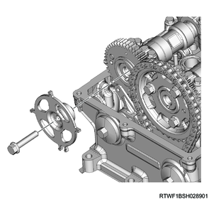
11) Install the timing chain tensioner and gasket to the flywheel housing.
Caution
- Do not reuse the gasket.
Tightening torque: 70 N・m { 7.1 kgf・m / 52 lb・ft }
Legend
- Timing chain tensioner
- Gasket
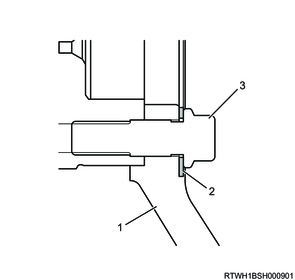
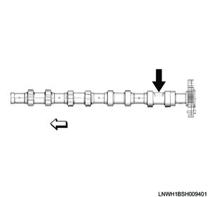
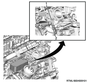
12) Install the cam angle sensor rotor to the inlet camshaft.
Note
- Install by aligning with the positioning pin.
- Referring to the diagram, secure the section indicated by the arrow.
Tightening torque: 25 N・m { 2.5 kgf・m / 18 lb・ft }
Fixing position
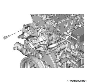
8. Thermostat housing installation
1) Apply soapy water to the O-ring.
2) Install the thermostat housing to the cylinder head and front cover.
Tightening torque: 25 N・m { 2.5 kgf・m / 18 lb・ft }
3) Connect the connector to the engine coolant temperature sensor.
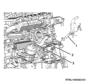
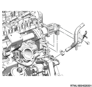
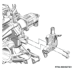
9. Turbocharger control solenoid valve installation
1) Install the bracket to the cylinder head.
Tightening torque: 25 N・m { 2.5 kgf・m / 18 lb・ft }
2) Install the turbocharger control solenoid valve to the bracket.
Tightening torque: 10 N・m { 1.0 kgf・m / 7 lb・ft }
3) Install the connector to the turbocharger control solenoid valve.
4) Connect the vacuum hose to the turbocharger control solenoid valve.
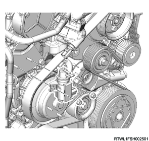
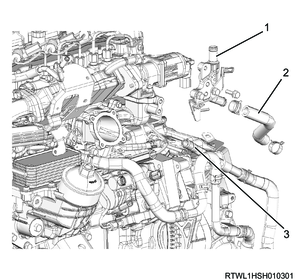
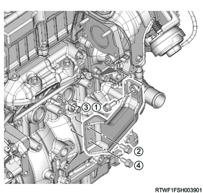
10. Common rail (fuel rail) installation
1) Install the common rail (fuel rail) to the cylinder head.
Tightening torque: 25 N・m { 2.5 kgf・m / 18 lb・ft }
Caution
- Do not hold the FRP sensor.
- Take care not to damage the connector section of the FRP sensor.

2) Install the connector to the FRP sensor.
3) Install the bracket to the cylinder head.
Note
- Install so that the detent makes contact with the common rail (fuel rail).
Tightening torque: 25 N・m { 2.5 kgf・m / 18 lb・ft }
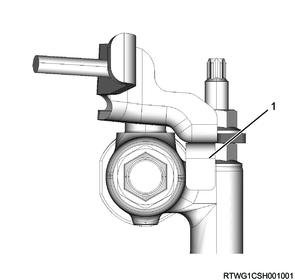
Legend
- Detent
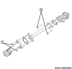
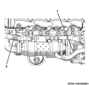
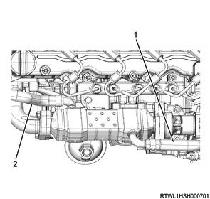
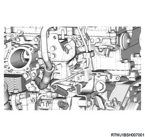
11. Water pipe installation
1. Automatic transmission models
1) Install the water pipe and EGR cooler water hose as a set to the flywheel housing.
Tightening torque: 52 N・m { 5.3 kgf・m / 38 lb・ft }

Legend
- EGR cooler water pipe B
- Nut
- Water pipe
- EGR cooler water hose
2) Connect the EGR cooler water hose to EGR cooler water pipe B.
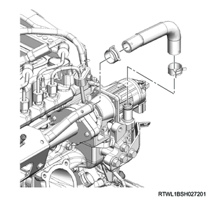
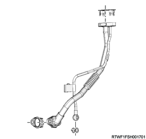
12. Fuel feed pipe installation
1) Install the fuel feed pipe to the fuel supply pump and common rail (fuel rail).
Caution
- Do not reuse the fuel feed pipe.
Tightening torque: 35 N・m { 3.6 kgf・m / 26 lb・ft }

Legend
- Fuel feed pipe
2) Install the clip to the fuel feed pipe.
Tightening torque: 10.0 N・m { 1.0 kgf・m / 89 lb・in }
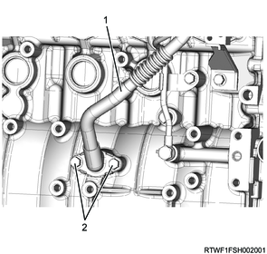
13. Fuel leak-off pipe installation
1) Install the fuel leak-off pipe to the common rail (fuel rail) and flywheel housing.
Tightening torque: 20.2 N・m { 2.1 kgf・m / 15 lb・ft } Common rail (fuel rail) side
Tightening torque: 25 N・m { 2.5 kgf・m / 18 lb・ft } Flywheel housing side

Legend
- Fuel leak-off pipe
2) Connect the fuel leak-off hose to the fuel leak-off pipe.
14. EGR installation
1. Euro2 specifications
Caution
- Do not reuse the gasket.
- If the procedures or methods for assembling the EGR device are mistaken, it can lead to cracks in the pipe or gas leaks. Always follow the procedures.
- Even when disassembling only a portion of the EGR-related parts, loosen all the EGR-related parts once, replace the gaskets with new ones, and then temporarily tighten in the following order before performing final tightening.
1) Temporarily tighten the following parts to the EGR pipe in the order shown in the diagram.
- EGR valve
- EGR duct
- Gasket
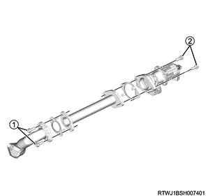
2) Temporarily tighten the EGR to the inlet cover.
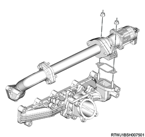
3) Final tighten the following parts to the EGR pipe in the order shown in the diagram.
- EGR valve
- EGR duct
- Gasket
Tightening torque: 25 N・m { 2.5 kgf・m / 18 lb・ft }
4) Final tighten the EGR to the inlet cover.
Tightening torque: 25 N・m { 2.5 kgf・m / 18 lb・ft }
2. Euro4 specifications
Caution
- Do not reuse the gasket.
- If the procedures or methods for assembling the EGR device are mistaken, it can lead to cracks in the pipe or gas leaks. Always follow the procedures.
- Even when disassembling only a portion of the EGR-related parts, loosen all the EGR-related parts once, replace the gaskets with new ones, and then temporarily tighten in the following order before performing final tightening.
1) Temporarily tighten the following parts to the EGR cooler in the order shown in the diagram.
- EGR valve
- EGR duct
- Gasket
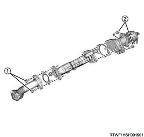
2) Temporarily tighten the EGR to the inlet cover in the order shown in the diagram.
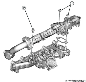
3) Final tighten the following parts to the EGR cooler in the order shown in the diagram.
- EGR valve
- EGR duct
- Gasket
Tightening torque: 25 N・m { 2.5 kgf・m / 18 lb・ft }
4) Final tighten the EGR to the inlet cover in the order shown in the diagram.
Tightening torque: 25 N・m { 2.5 kgf・m / 18 lb・ft }
15. Relief valve installation
1. Except for Euro2 and Euro4 specifications
Caution
- Do not reuse the gasket.
1) Temporarily tighten the following parts to the EGR pipe in the order shown in the diagram.
- EGR duct
- Relief valve
- Gasket
2) Temporarily tighten the following parts to the inlet cover in the order shown in the diagram.
- Relief valve
- Relief valve control solenoid valve
- Relief valve control solenoid valve bracket
- Adapter
- Gasket
3) Final tighten the following parts to the EGR pipe in the order shown in the diagram.
- EGR duct
- Relief valve
- Gasket
Tightening torque: 25 N・m { 2.5 kgf・m / 18 lb・ft }
4) Final tighten the following parts to the cylinder head and inlet cover in the order shown in the diagram.
- Relief valve
- Relief valve control solenoid valve
- Relief valve control solenoid valve bracket
- Adapter
- Gasket
Tightening torque: 25 N・m { 2.5 kgf・m / 18 lb・ft }
16. Inlet cover installation
1. Except for Euro4 specifications
1) Install the inlet cover and EGR to the cylinder head in the order shown in the diagram.
Tightening torque: 25 N・m { 2.5 kgf・m / 18 lb・ft }
2) Install the harness bracket to the inlet cover.
Note
- Install the harness bracket so that the detent makes full contact with the inlet cover.
Tightening torque: 25 N・m { 2.5 kgf・m / 18 lb・ft }

Legend
- Inlet cover
- Detent
3) Install the air duct bracket to the inlet cover.
Tightening torque: 25 N・m { 2.5 kgf・m / 18 lb・ft }
2. Euro4 specifications
1) Install the inlet cover and EGR to the cylinder head in the order shown in the diagram.
Tightening torque: 25 N・m { 2.5 kgf・m / 18 lb・ft }

2) Install the harness bracket to the inlet cover.
Note
- Install the harness bracket so that the detent makes full contact with the inlet cover.
Tightening torque: 25 N・m { 2.5 kgf・m / 18 lb・ft }
Legend
- Inlet cover
- Detent
3) Install the air duct bracket to the inlet cover.
Tightening torque: 25 N・m { 2.5 kgf・m / 18 lb・ft }
4) Install the vacuum pipe to the air duct bracket.
Tightening torque: 10.0 N・m { 1.0 kgf・m / 89 lb・in }
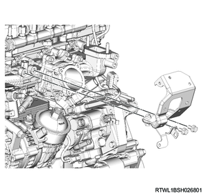
5) Connect the vacuum hose to the vacuum pipe.
Legend
- Vacuum pipe
- Vacuum hose
- Air duct bracket
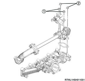
17. EGR cooler water hose connect
1. Euro4 specifications
1) Install EGR cooler water pipe A to the inlet cover.
Tightening torque: 25 N・m { 2.5 kgf・m / 18 lb・ft }
2) Connect the EGR cooler water hose to EGR cooler water pipe A.
Manual transmission models
Legend
- EGR cooler water pipe A
- EGR cooler water hose
- EGR cooler water pipe B
Automatic transmission models
Legend
- EGR cooler water pipe A
- EGR cooler water hose
- Water pipe
3) Connect the EGR cooler water return hose to the EGR cooler.
4) Connect the EGR cooler water feed hose to the EGR cooler.
Manual transmission models
Legend
- EGR cooler water return hose
- EGR cooler water feed hose
Automatic transmission models
Legend
- EGR cooler water return hose
- EGR cooler water feed hose
18. Water pipe installation
1. Except for Euro4 specifications
1) Install the water pipe to the inlet cover.
Tightening torque: 25 N・m { 2.5 kgf・m / 18 lb・ft }
Manual transmission models
Automatic transmission models
2) Install the pipe clip to the water pipe.
Tightening torque: 25 N・m { 2.5 kgf・m / 18 lb・ft }
3) Install the water pipe to the air duct bracket.
Tightening torque: 10.0 N・m { 1.0 kgf・m / 89 lb・in }
4) Install the water hose to the water pipe.
Manual transmission models

Automatic transmission models
5) Install the vacuum pipe to the air duct bracket.
Tightening torque: 10.0 N・m { 1.0 kgf・m / 89 lb・in }
6) Connect the vacuum hose to the vacuum pipe.
Euro2 specifications
Legend
- Vacuum pipe
- Vacuum hose
- Bracket
Except for Euro2 specifications
Legend
- Vacuum hose
- Vacuum pipe
- Bracket
- Relief valve control solenoid valve
- Relief valve control solenoid valve bracket
19. Glow plug installation
1) Install the glow plug to the cylinder head.
Tightening torque: 17.5 N・m { 1.8 kgf・m / 13 lb・ft }
2) Install the glow plug terminal and glow plug connector to the glow plug.
Tightening torque: 1.0 N・m { 0.10 kgf・m / 8.9 lb・in }
Legend
- Glow plug terminal
- Glow plug connector
20. Intake throttle valve installation
1) Install the intake throttle valve and gasket to the inlet manifold.
Caution
- Do not reuse the gasket.
Tightening torque: 10.0 N・m { 1.0 kgf・m / 89 lb・in }
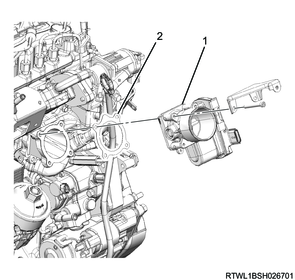
Legend
- Intake throttle valve
- Gasket
2) Connect the connector to the intake throttle valve.
21. Intake air duct installation
1) Install the intake duct to the intake throttle valve.
Tightening torque: 10.0 N・m { 1.0 kgf・m / 89 lb・in } Bolt
Tightening torque: 4.0 N・m { 0.4 kgf・m / 35 lb・in } Clamp (Intake throttle side)
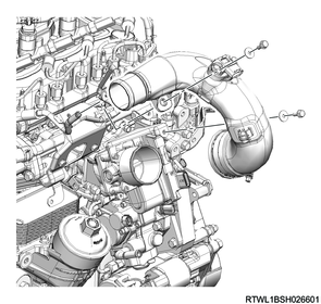
Clamp installation direction
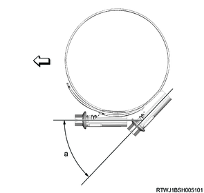
Standard value
a: 45 °
2) Connect the connector to the boost pressure and CAC temperature sensor.
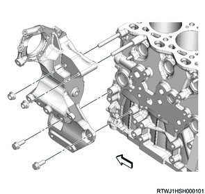
22. Generator bracket installation
1) Install the generator bracket to the cylinder block.
Tightening torque: 52 N・m { 5.3 kgf・m / 38 lb・ft }
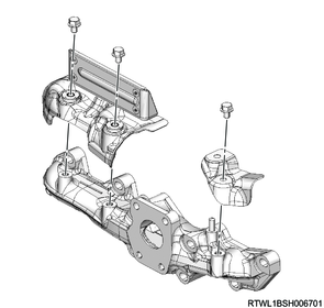
23. Exhaust manifold installation
1) Install the gasket to the cylinder head.
Note
- Face the protruding section of the gasket toward the engine front side.
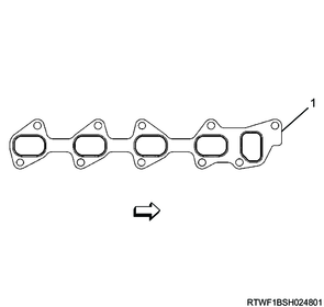
Legend
- Protrusion
Caution
- Do not reuse the gasket.
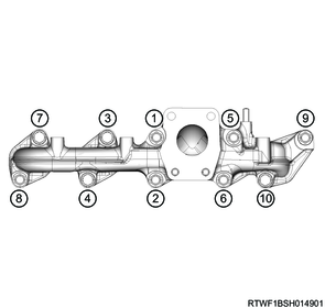
2) Referring to the diagram, temporarily tighten the exhaust manifold to the cylinder head.
Tightening torque: 30 N・m { 3.1 kgf・m / 22 lb・ft }
Washer installation direction
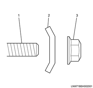
Legend
- Stud bolt
- Washer
- Nut
Spacer and washer installation direction
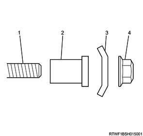
Legend
- Stud bolt
- Spacer
- Washer
- Nut
3) Securely tighten the exhaust manifold to the cylinder head.
Tightening torque: 52 N・m { 5.3 kgf・m / 38 lb・ft } 1st time
Tightening torque: 52 N・m { 5.3 kgf・m / 38 lb・ft } 2nd time
Note
- Retighten to the same torque to prevent variations in the tightening torque.
Caution
- Do not over-tighten since it will expand or contract due to the heat of the manifold.
4) Install the heat protector to the exhaust manifold.
Tightening torque: 25 N・m { 2.5 kgf・m / 18 lb・ft }
24. Turbocharger installation
1) Install the water feed and return pipe, as well as the gasket to the turbocharger.
Caution
- Do not reuse the gasket.
Tightening torque: 10.0 N・m { 1.0 kgf・m / 89 lb・in }
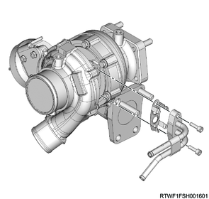
2) Feed 1 cc (approximately 20 drops) of engine oil into the oil feed port.
3) Install the turbocharger and gasket to the exhaust manifold.
Caution
- Do not reuse the gasket.
Tightening torque: 52 N・m { 5.3 kgf・m / 38 lb・ft }
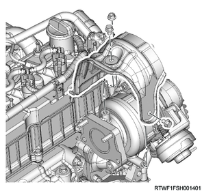
25. Turbocharger heat protector installation
1) Install the turbocharger heat protector to the turbocharger.
Tightening torque: 25 N・m { 2.5 kgf・m / 18 lb・ft }
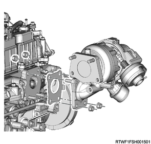
26. Turbocharger bracket installation
1) Temporarily tighten the turbocharger bracket to the turbocharger and cylinder block in the order shown in the diagram.
2) Final tighten the turbocharger bracket to the turbocharger and cylinder block in the order shown in the diagram.
Tightening torque: 52 N・m { 5.3 kgf・m / 38 lb・ft }
27. Turbocharger oil pipe installation
1) Install the gasket to the turbocharger oil pipe.
Caution
- Do not reuse the gasket.
2) Install the turbocharger oil pipe and gasket to the turbocharger.
Caution
- Do not reuse the gasket.
Tightening torque: 10.0 N・m { 1.0 kgf・m / 89 lb・in }
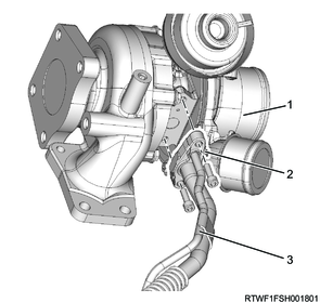
Legend
- Turbocharger
- Gasket
- Turbocharger oil pipe
3) Install the turbocharger oil pipe (feed side) to the cylinder block.
Caution
- Do not reuse the gasket.
Tightening torque: 22.5 N・m { 2.3 kgf・m / 17 lb・ft } Eyebolt
Tightening torque: 25 N・m { 2.5 kgf・m / 18 lb・ft } Bolt
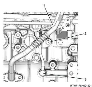
Legend
- Turbocharger oil pipe (feed side)
- Bolt
- Eyebolt
4) Install the turbocharger oil pipe (return side) and gasket to the cylinder block.
Caution
- Do not reuse the gasket.
Tightening torque: 25 N・m { 2.5 kgf・m / 18 lb・ft }
Legend
- Turbocharger oil pipe (return side)
- Bolt
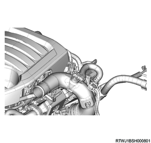
28. Turbocharger water hose connect
1) Connect the turbocharger water return hose to the water feed pipe and return pipe.
2) Connect the turbocharger water feed hose to the water feed pipe and return pipe.
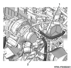
Legend
- Turbocharger water feed hose
- Turbocharger water return hose
29. Vacuum hose installation
1) Install the vacuum hose to the turbocharger and vacuum pipe.
2) Connect the vacuum hose to the turbocharger control solenoid valve.
30. Cylinder head cover installation
31. Engine oil filling
1) Replenish the engine with the engine oil.
2) Check the tightening of the oil pan drain plug.
Tightening torque: 83 N・m { 8.5 kgf・m / 61 lb・ft }