1. Component views
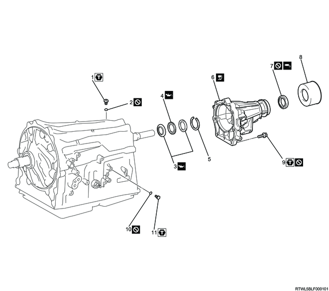
Transmission case
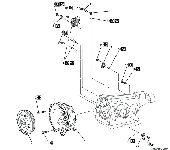
Part name
- Torque converter assembly
- Bolt
- Bolt
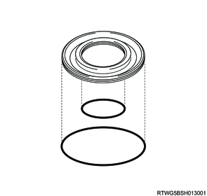
- Converter housing
- O-ring
- Elbow
- Inhibitor switch
- Lock washer
- Nut
- Bolt
- Breather hose
- Breather plug
- O-ring
- Bolt
- Output speed sensor
- O-ring
- Filler plug
- O-ring
- Bolt
- Turbine Speed Sensor
- O-ring
Tightening torque
2: 34 N・m { 3.5 kgf・m / 25 lb・ft } M10
3: 57 N・m { 5.8 kgf・m / 42 lb・ft } M12
6: 29 N・m { 3.0 kgf・m / 21 lb・ft }
9: 7 N・m { 0.7 kgf・m / 62 lb・in }
10: 13 N・m { 1.3 kgf・m / 115 lb・in }
14: 5 N・m { 0.5 kgf・m / 44 lb・in }
17: 40 N・m { 4.1 kgf・m / 30 lb・ft }
19: 5 N・m { 0.5 kgf・m / 44 lb・in }
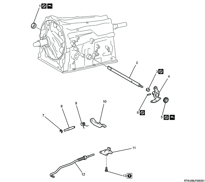
Part name
- Manual shaft oil seal
- Manual valve lever shaft
- Spacer
- Manual valve lever
- Manual shaft oil seal
- Spring pin
- Snap ring
- Parking lock pawl shaft
- Torsion spring
- Parking lock pawl
- Parking lock pawl bracket
- Parking lock rod
- Bolt
Tightening torque
13: 18 N・m { 1.8 kgf・m / 13 lb・ft }
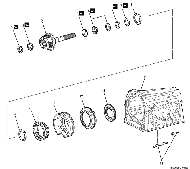
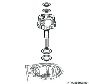
Transmission case adapter (4WD models)
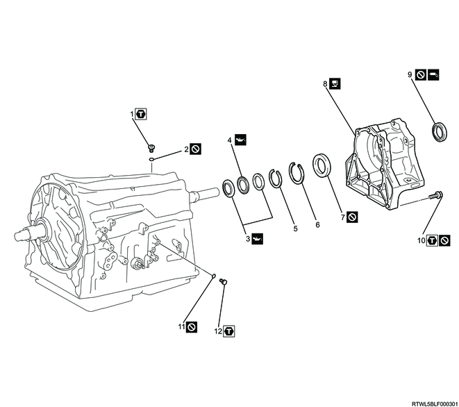
Part name
- Bolt
- O-ring
- Thrust bearing race
- Thrust needle roller bearing
- Snap ring
- Snap ring
- Transmission case adapter bearing
- Transmission case adapter
- Transmission case adapter oil seal
- Bolt
- O-ring
- Bolt
Tightening torque
1: 39 N・m { 4.0 kgf・m / 29 lb・ft }
10: 34 N・m { 3.5 kgf・m / 25 lb・ft }
12: 7 N・m { 0.7 kgf・m / 62 lb・in }
Extension housing (2WD models)
Part name
- Bolt
- O-ring
- Thrust bearing race
- Thrust needle roller bearing
- Snap ring
- Extension housing
- Extension housing oil seal
- Extension housing dust deflector
- Bolt
- O-ring
- Bolt
Tightening torque
1: 39 N・m { 4.0 kgf・m / 29 lb・ft }
9: 34 N・m { 3.5 kgf・m / 25 lb・ft }
11: 7 N・m { 0.7 kgf・m / 62 lb・in }
Valve body assembly
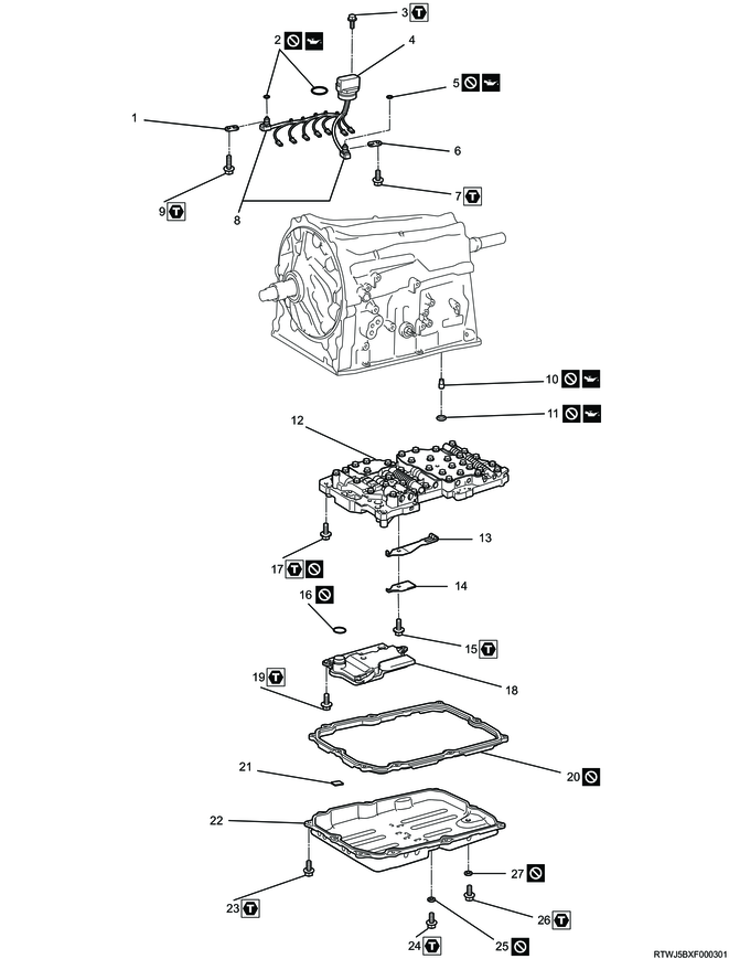
Part name
- Temperature sensor clamp
- O-ring
- Bolt
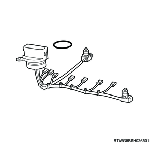
- Transmission internal harness
- O-ring
- Temperature sensor clamp
- Bolt
- Oil temperature sensor
- Bolt
- Brake drum gasket
- Transmission case gasket
- Valve body assembly
- Detent spring
- Detent spring cover
- Bolt
- O-ring
- Bolt
- Oil strainer
- Bolt
- Oil pan gasket
- Oil cleaner magnet
- Transmission oil pan sub-assembly
- Bolt
- Bolt
- Gasket
- Bolt
- Gasket
Tightening torque
3: 5 N・m { 0.5 kgf・m / 44 lb・in }
7: 10 N・m { 1.0 kgf・m / 89 lb・in }
9: 11 N・m { 1.1 kgf・m / 97 lb・in }
15: 10 N・m { 1.0 kgf・m / 89 lb・in }
17: 11 N・m { 1.1 kgf・m / 97 lb・in }
19: 10 N・m { 1.0 kgf・m / 89 lb・in }
23: 7 N・m { 0.7 kgf・m / 62 lb・in }
24: 20 N・m { 2.0 kgf・m / 15 lb・ft }
26: 20 N・m { 2.0 kgf・m / 15 lb・ft }
Valve body assembly
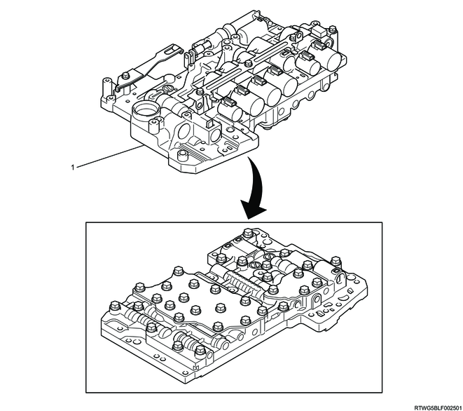
Part name
- Valve body assembly
Gear train
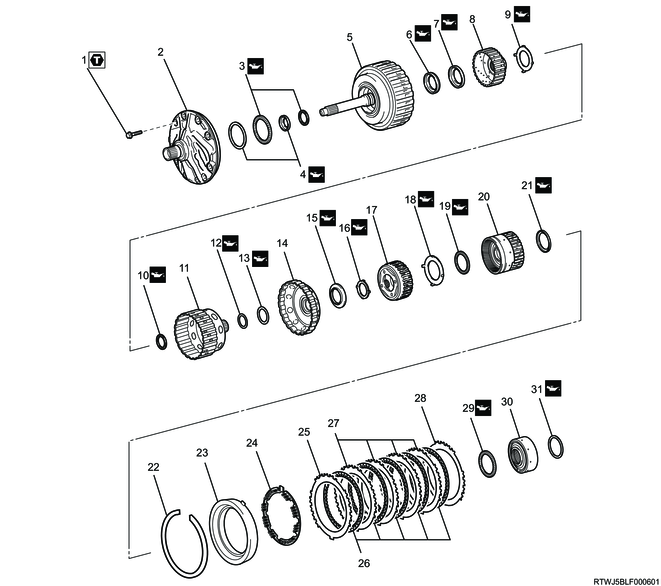
Part name
- Bolt
- Oil pump assembly
- Thrust needle roller bearing
- Thrust bearing race
- Direct clutch assembly and forward clutch assembly
- Thrust needle roller bearing
- Thrust bearing race
- Forward clutch hub
- Thrust bearing race
- Thrust needle roller bearing
- Clutch hub sub-assembly
- Thrust needle roller bearing with race
- Thrust bearing race
- Sun gear input drum
- Thrust needle roller bearing with race
- Thrust bearing race
- Front planetary gear assembly
- Thrust bearing race
- Thrust needle roller bearing with race
- Front planetary ring gear with front planetary ring gear flange sub-assembly
- Thrust bearing race
- Snap ring
- Brake cylinder No. 2 with brake piston No. 2
- Brake piston return spring sub-assembly No. 2
- Brake flange No. 2
- Brake disc No. 2
- Brake plate No. 2
- Brake flange No. 2
- Thrust needle roller bearing with race
- Middle planetary ring gear flange with middle planetary ring gear
- Thrust needle roller bearing
Tightening torque
1: 21 N・m { 2.1 kgf・m / 15 lb・ft }
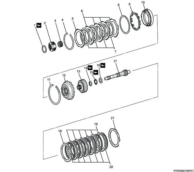
Part name
- Thrust bearing race
- Middle planetary gear assembly
- Planetary sun gear
- Snap ring
- Brake flange No. 1
- Brake plate No. 1
- Brake disc No. 1
- Snap ring
- Brake piston return spring sub-assembly
- Brake cylinder No. 1 with brake piston No. 1
- Snap ring
- 1 way clutch assembly No. 3 with inner race
- Rear planetary ring gear flange sub-assembly
- Thrust bearing race
- Thrust needle roller bearing
- Thrust bearing race
- Intermediate shaft
- Brake flange No. 4
- Brake plate No. 4
- Brake disc No. 4
- Brake flange No. 4
Part name
- Thrust needle roller bearing with race
- Thrust bearing race
- Rear planetary gear assembly
- Thrust needle roller bearing with race
- Thrust bearing race
- Thrust needle roller bearing
- Thrust bearing race
- Snap ring
- Snap ring
- 1st and reverse brake return spring sub-assembly
- 1st and reverse brake piston
- Brake reaction sleeve
- Inner brake piston No. 4
- Transmission case
- Brake plate stopper spring
2. Transfer removal
1. 4WD models
Refer to "3.Driveline, Axle 3D.Transfer Case transfer removal".
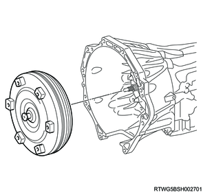
3. Torque converter assembly removal
1) Remove the torque converter assembly from the transmission case.
Caution
- Be careful not to damage the oil pump oil seal.
- Be careful not to drop the torque converter assembly.
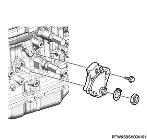
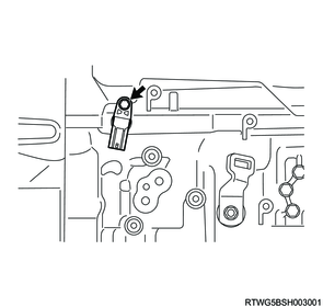
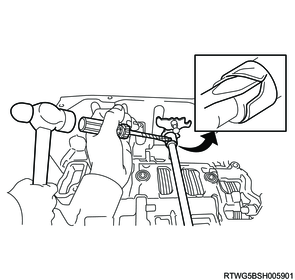
4. Inhibitor switch removal
1) Using a screwdriver, pry off the lock washer.

2) Remove the nut and the lock washer from the inhibitor switch.
3) Remove the bolt and the inhibitor switch from the transmission case.
Note
- Make sure that the manual valve lever shaft has not been rotated prior to installing the inhibitor switch, as the detent spring may become detached from the manual valve lever shaft.
Caution
- Do not touch the terminals.
- Be careful not to damage the inhibitor switch.
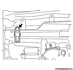
5. Turbine speed sensor removal
1) Remove the turbine speed sensor from the transmission case.
Caution
- Be careful not to damage the turbine speed sensor.
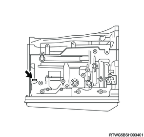
6. Output speed sensor removal
1) Remove the output speed sensor from the transmission case.
Caution
- Be careful not to damage the output speed sensor.
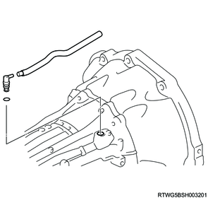
7. Breather hose removal
1) Remove the breather hose from the transmission case.
2) Remove the breather plug and the O-ring from the transmission case.
8. Test plug removal
1) Remove the 6 test plugs from the transmission case as necessary.
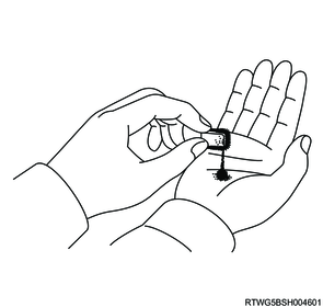
2) Remove the 6 O-rings from the test plug.

9. Transmission case plug removal
1) Using a torx wrench (T55), remove the transmission case plug from the transmission case as necessary.
2) Remove the O-ring from the transmission case plug.
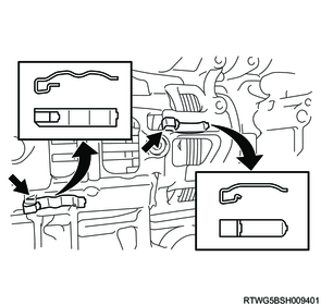
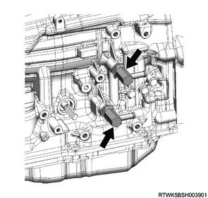
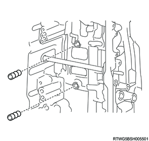
10. Elbow removal
1) Remove the 2 elbows from the transmission case.
2) Remove the 2 O-rings from the elbows.
11. Deflector removal
1. 2WD models
1) Using a plastic hammer, remove the extension housing dust deflector from the extension housing.
Caution
- Be careful not to damage the extension housing.
12. Extension housing assembly removal
1. 2WD models
1) Remove the 8 bolts and the extension housing from the transmission case.

Legend
- M10 x 1.5 x 45 mm (Seal bolt)
- M10 x 1.5 x 40 mm (Seal bolt)
13. Adapter housing removal
1. 4WD models
1) Remove the 10 bolts and the transmission case adapter.

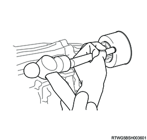
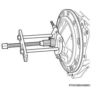
14. Adapter housing bearing removal
1. 4WD models
1) Using snap ring pliers, remove the snap ring from the transmission case adapter.
Caution
- Be careful not to damage the transmission case adapter.
2) Using special tool, remove the transmission case adapter bearing from the transmission case adapter.
Caution
- Be careful not to damage the transmission case adapter.
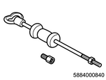
SST: 5-8840-0084-0 - sliding hammer
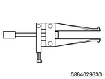
SST: 5-8840-2963-0 - oil seal remover

Legend
- 5-8840-0084-0
- 5-8840-2963-0
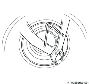
15. Rear oil seal removal
1. 4WD models
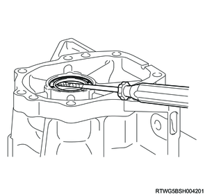
1) Using a screwdriver, remove the transmission case adapter oil seal from the transmission case adapter.
Caution
- Tape the screwdriver tip before use.
- Be careful not to damage the transmission case adapter.
- If using a screwdriver, use a wooden block or equivalent to avoid damaging the fitting surface of the transmission case adapter.
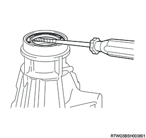
2. 2WD models
1) Using a screwdriver, remove the extension housing oil seal from the extension housing.
Caution
- Tape the screwdriver tip before use.
- Be careful not to damage the extension housing.
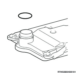
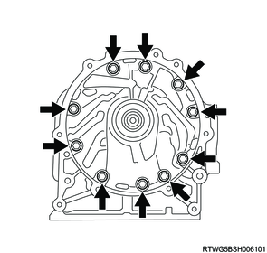
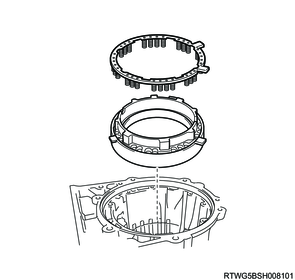
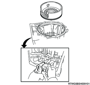
16. Converter housing removal
1) Remove the 12 bolts and the converter housing from the transmission case.
Note
- The number shown in the figure indicates the kind of bolts.

Legend
- M10 x 1.5 x 35 mm
- M10 x 1.5 x 35 mm (Seal bolt)
- M12 x 1.75 x 38 mm (Seal bolt)
17. Oil pan removal
1) Remove the 10 bolts from the oil pan.
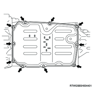
2) Remove the transmission oil pan and the transmission oil pan gasket from the transmission case.
Caution
- Be careful not to damage the fitting surfaces of the transmission case and the oil pan.
- Be careful not to deform the oil pan.
3) Remove the 4 oil cleaner magnets from the oil pan.

4) Examine the chips and particles in the oil pan and on the oil cleaner magnet to determine what type of wear has occurred in the transmission.
Caution
- Keep a record of the amount of fluid that is drained.
| Types of Chips and Particles |
Cause |
| Steel (magnetic) |
Bearing, gear and plate wear |
| Brass (non-magnetic) |
Bushing wear |
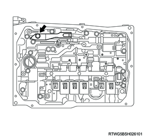
18. Transmission internal harness removal
1) Remove the 2 bolts and the 2 temperature sensor clamps, and pull out the 2 oil temperature sensors (OT1, OT2) from the valve body assembly.
2) Disconnect the 8 solenoid connectors.
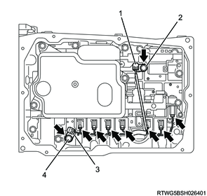
Legend
- Temperature sensor (OT1)
- M6 x 1.0 x 14 mm
- Temperature sensor (OT2)
- M6 x 1.0 x 36 mm
3) Remove the bolt and pull out the transmission wire from the transmission case.
Caution
- Be careful not to damage the harness.
- Be careful not to pull the harness forcibly.

4) Remove the O-ring from the transmission wire connector.
19. Oil strainer removal
1) Remove the 3 bolts and the oil strainer from the valve body assembly.
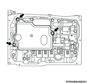
2) Remove the O-ring from the oil strainer.
20. Detent spring removal
1) Remove the bolt and the detent spring and detent spring cover.
21. Valve body assembly removal
1) Remove the 12 bolts and the valve body assembly from the transmission case.
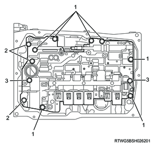
Legend
- M6 x 1.0 x 25 mm
- M6 x 1.0 x 36 mm
- M6 x 1.0 x 50 mm
22. Brake drum gasket removal
1) Remove the 2 transmission case gaskets from the transmission case.
2) Remove the 2 brake drum gaskets from the transmission case.
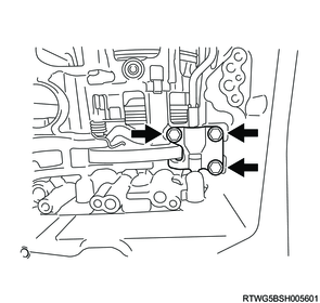
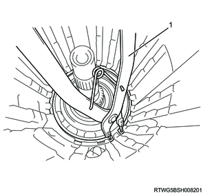
23. Parking lock pawl bracket removal
1) Remove the 3 bolts from the transmission case.
2) Push the parking lock pawl bracket into the rear side.
3) Pull the parking lock rod towards the front side.
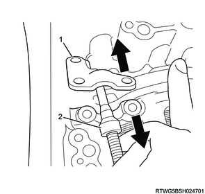
Legend
- Parking lock pawl bracket
- Parking lock rod
4) Slide the parking lock pawl bracket inside the transmission while pushing the parking lock pawl, then slide the parking lock rod to the bolt hole side.
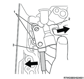
Legend
- Bolt hole
- Parking lock pawl bracket
- Parking lock rod
5) Remove the parking lock pawl bracket from the transmission case.
24. Parking lock rod removal
1) Disconnect the parking lock rod from the manual valve lever.

25. Parking lock pawl shaft removal
1) Remove the torsion spring from the parking lock pawl shaft.
Caution
- Be careful not to apply too much force to the torsion spring.
2) Remove the parking lock pawl shaft and parking lock pawl from the transmission case.
3) Remove the snap ring from the parking lock pawl shaft.

26. Manual valve lever removal
1) Using a screwdriver and hammer, cut off the spacer and remove it from the manual valve lever shaft.
Caution
- Be careful not to damage the manual valve lever shaft.
2) Using a pin punch (3 mm {0.118 in}) and hammer, tap out the spring pin.
Note
- Slowly tap out the spring pin so that it does not fall into the transmission case.

3) Pull the manual valve lever shaft out through the transmission case, and remove the manual valve lever.
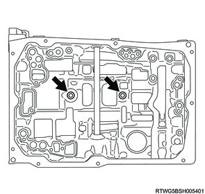
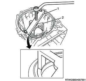
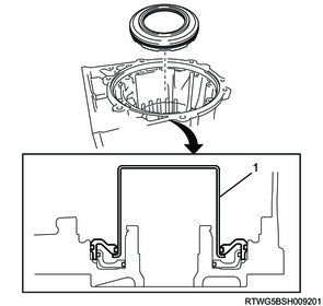
27. Manual shaft oil seal removal
1) Using a screwdriver, pry out the 2 manual shaft oil seals from the transmission case.
Caution
- Be careful not to damage the transmission case.
- Tape the screwdriver tip before use.
- If using a screwdriver, use a wooden block or equivalent to avoid damaging the fitting surface of the transmission case.
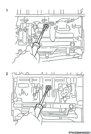
Legend
- Right side
- Left side
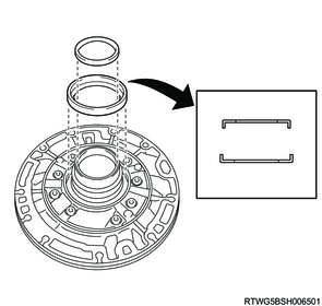
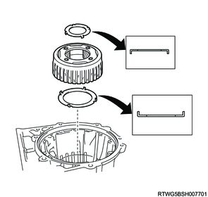
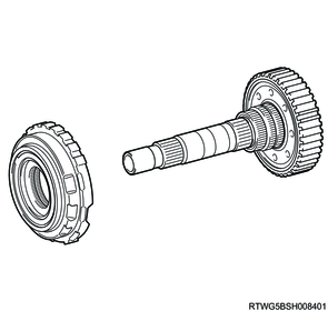
28. Oil pump removal
1) Remove the 10 bolts from the oil pump assembly.
2) Using a remover, pull out the oil pump assembly from the transmission case.
3) Remove the 2 thrust bearing races from the oil pump assembly.
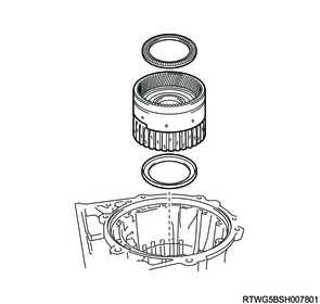
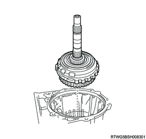
29. Forward clutch assembly removal
1) Remove the direct clutch assembly and the forward clutch assembly (input shaft) from the transmission case.
2) Remove the 3 thrust needle roller bearings from the direct clutch assembly and the forward clutch assembly (input shaft).
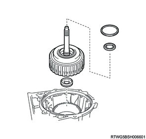
3) Remove the direct clutch assembly from the forward clutch assembly (input shaft).

4) Remove the forward clutch hub from the transmission case.
5) Remove the 2 thrust bearing races from the forward clutch hub.

6) Remove the clutch hub sub-assembly from the transmission case.
7) Remove the thrust needle roller bearing with race and the thrust needle roller bearing from the clutch hub sub-assembly.
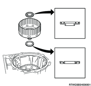
30. Sun gear input drum removal
1) Remove the sun gear input drum from the transmission case.
2) Remove the thrust needle roller bearing with race and the thrust bearing race from the sun gear input drum.
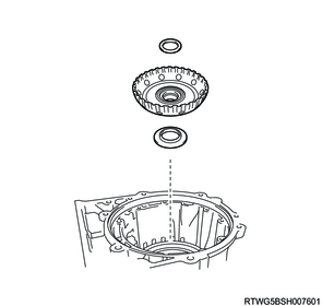
31. Front planetary gear assembly removal
1) Remove the front planetary gear assembly from the transmission case.
2) Remove the 2 thrust bearing races from the front planetary gear assembly.
32. Front planetary ring gear removal
1) Remove the front planetary ring gear with the front planetary ring gear flange sub-assembly from the transmission case.
2) Remove the thrust needle roller bearing with race and the thrust bearing race from the front planetary ring gear with front planetary ring gear flange sub-assembly.
33. Brake piston No.2 removal
1) Place the special tool on brake cylinder No. 2 with brake piston No. 2, and compress the brake piston return spring sub-assembly No. 2 with a shop press.
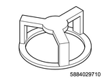
SST: 5-8840-2971-0 - spring compressor
SST: 5-8840-2973-0 - spring compressor kit
Legend
- 5-8840-2973-0
- 5-8840-2971-0
Caution
- Be careful not to shorten the return spring too much.
2) Using a screwdriver, remove the snap ring from the transmission case.
Caution
- Be careful not to damage the transmission case.
3) Remove brake cylinder No. 2 with brake piston No. 2 and brake piston return spring sub-assembly No. 2 from the transmission case.
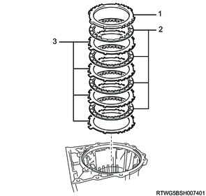
34. Brake disc No.2 removal
1) Remove the 4 plates, 5 discs and 2 flanges from the transmission case.
Note
- Check the number and order of flange, discs and plates.

Legend
- Plate
- Flange
- Disc
35. Middle planetary ring gear removal
1) Remove the middle planetary ring gear flange with the middle planetary ring gear from the transmission case.
2) Remove the 2 thrust needle roller bearings from the middle planetary ring gear flange with middle planetary ring gear.
36. Middle planetary gear assembly removal
1) Remove the middle planetary gear assembly from the transmission case.
2) Remove the thrust bearing race from the middle planetary gear assembly.

37. Planetary sun gear removal
1) Remove the planetary sun gear from the transmission case.
38. Brake disc No.1 removal
1) Using a screwdriver, remove the snap ring from the transmission case.
Caution
- Be careful not to damage the transmission case.
2) Remove the flange, 4 discs and 4 plates from the transmission case.
Legend
- Flange
- Disc
- Plate
39. Brake piston No.1 removal
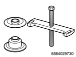
1) Place the special tool on the brake piston return spring sub-assembly, and compress the brake piston return spring sub-assembly with a shop press.
Note
- Place the special tool on the surface with protrusions.
Caution
- Be careful not to shorten the return spring too much.
SST: 5-8840-2973-0 - spring compressor kit
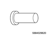
SST: 5-8840-2962-0 - oil seal installer
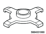
SST: 5-8840-3199-0 - spring compressor
Legend
- 5-8840-2973-0
- 5-8840-2962-0
- 5-8840-3199-0
2) Using a screwdriver, remove the snap ring from the transmission case.
Caution
- Be careful not to damage the transmission case.
3) Remove the brake piston return spring sub-assembly and brake cylinder No. 1 with brake piston No. 1 from the transmission case.
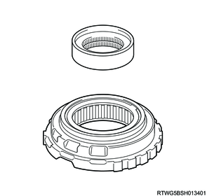
40. 1way clutch No.3 removal
1) Using the special tool, remove the snap ring from the transmission case.
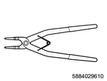
SST: 5-8840-2961-0 - snap ring pliers
Legend
- 5-8840-2961-0
2) Remove the intermediate shaft with 1 way clutch assembly No. 3 with inner race and rear planetary ring gear flange with rear planetary ring gear from the transmission case.
3) Remove the 1 way clutch assembly No. 3 with inner race from the rear planetary ring gear flange with rear planetary ring gear.
4) Remove the 1 way clutch inner race from the 1 way clutch assembly No. 3.
41. Rear planetary ring gear removal
1) Remove the rear planetary ring gear flange with rear planetary ring gear from the intermediate shaft.
2) Remove the thrust needle roller bearing and the 2 thrust bearing races from the intermediate shaft.
42. Brake disc No.4 removal
1) Remove the 2 flanges, 7 discs and 6 plates from the transmission case.
Note
- Check the number and order of flange, discs and plates.
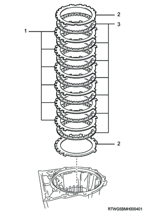
Legend
- Plate
- Flange
- Disc
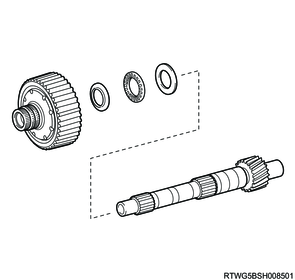
43. Rear planetary gear assembly removal
1) Using snap ring pliers, remove the snap ring from the rear planetary gear assembly.

2) Remove the 2 thrust bearing races and thrust needle roller bearing from the output shaft.

3) Remove the rear planetary gear assembly from the transmission case.
4) Remove the 2 thrust needle roller bearings and 2 thrust bearing races from the rear planetary gear assembly.
44. 1st and reverse brake piston removal
1) Set the special tool on the 1st and reverse brake return spring sub-assembly, tighten the special tool and compress the 1st and reverse brake return spring sub-assembly.
Caution
- Be careful not to shorten the return spring too much.
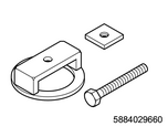
SST: 5-8840-2966-0 - spring compressor
2) Using snap ring pliers, remove the snap ring.
Caution
- Be careful not to expand the snap ring too much.
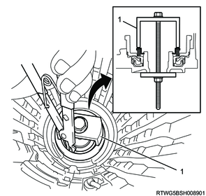
Legend
- 5-8840-2966-0
3) Remove the 1st and reverse brake return spring sub-assembly from the transmission case.
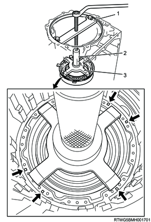
4) While pushing the 1st and reverse brake piston by hand, apply compressed air into the oil passage of the transmission case as shown in the figure and remove the 1st and reverse brake piston.
Caution
- Be careful not to damage the 1st and reverse brake piston.
300 kPa { 3 kgf/cm2 / 44 psi } Compressed air
5) Remove the O-ring from the 1st and reverse brake piston.
Note
- In some cases, the 1st and reverse brake piston may be removed with the brake reaction sleeve and inner brake piston No. 4 attached.

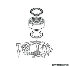
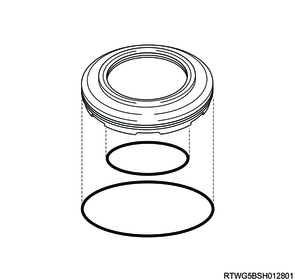
45. Brake reaction sleeve removal
1) Using the special tool, remove the brake reaction sleeve from the transmission case.

SST: 5-8840-2967-0 - reaction sleeve puller
Legend
- 5-8840-2967-0
2) Remove the 2 O-rings from the brake reaction sleeve.
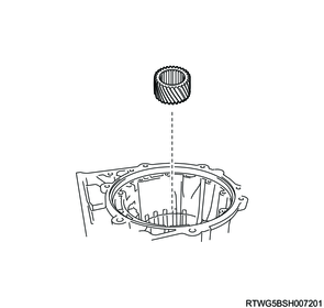
3) Using the special tool, remove inner brake piston No. 4 from the transmission case.
SST: 5-8840-2968-0 - piston puller

Legend
- 5-8840-2968-0
4) Remove the 2 O-rings from the inner brake piston No. 4.
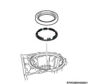
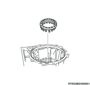
46. Plate stopper spring removal
1) Remove the 2 brake plate stopper springs from the transmission case.