1. Wheel alignment check description of function
The angle relationships between the front wheel/front suspension installation parts and the ground are described in this section.
Ensure effective steering and good directional stability and maintain adequate wheel alignment to prevent abnormal tire wear.
The most important elements in the wheel alignment are wheel toe-in, wheel camber, and axle caster.
Caution
- For electric power steering unit equipped models, the steering wheel must be fixed in the range where the steering angle is within ± 2° before performing. At this time, check that the right and left tie rod protrusions have the same amount.
- For electric power steering unit equipped models, if the vehicle sways from right to left during running check after adjusting the wheel alignment, or if the vehicle returns poorly to the expected position when turning the steering wheel right or left and releasing both hands from the steering wheel, perform the above operation again.
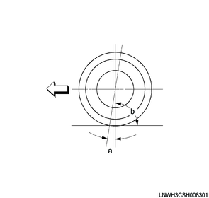
1. Camber
This illustration shows the vehicle viewed from the front.
Legend
a. Camber
Standard value
b. 90°
The camber is facing toward the inside or outside of the front wheel and tilted in up and down directions.
If the wheel is tilted up and outward, the camber is positive (+). If the wheel is tilted down and inward, the camber is negative (-).
The tilt angle measured against the vertical is the camber angle. If the camber angle is extreme or uneven between wheels, improper steering and excessive tire wear may result.
While positive camber causes wear on the outer part of the tire, negative camber causes wear on the inner part of the tire.
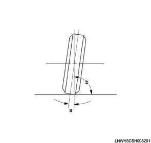
2. Caster
This illustration shows the vehicle viewed from the side.
Legend
a. Caster
Standard value
b. 90°
The caster is tilted in up and down directions according to whether the wheel axis is forward or backward.
The backward tilting is positive (+) and forward tilting is negative (-) (when the vehicle is viewed from the side).
In case of short and long arm type suspension, the caster angle can be measured only by special equipment. However, when viewed straight from the top of the upper link toward the ground, the ball joint is not aligned (overall) when the caster angle is not 0°. If the angle is positive, the lower ball joint may be at a position slightly forward of the upper ball joint center line.
3. Toe-in
This illustration shows the vehicle viewed from above.
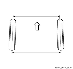
Toe-in is the measurement of front wheel rotation.
Actual toe-in amount is normally represented by angle rate. Toe-in is measured from the center of the tire tread or inside of the tire.
The purpose of toe-in is to ensure parallel rolling of the front wheels and to offset any vibration of the wheel support system caused by forward rolling of the vehicle.
Wrong toe-in may lead to excessive toe-in or unstable steering. Toe-in is the last alignment set in the wheel alignment work.
2. Wheel alignment check
1. Wheel alignment measurement conditions
Measure with the vehicle unloaded (without passengers or a load).
Check the inspected areas again before adjusting the wheel alignment.
2. Inspection before measuring wheel alignment
1) Inspect for the following.
- Posture of the vehicle
- Looseness of the front hub
- Looseness of the suspension
- Defective shock absorber
- Runout and distortion of the wheel
- Tie-rod connection looseness
- Abnormal kingpin noise
- Leaf spring deterioration or breakage
- Looseness of the bolts and nuts of each section
- Trim height (If outside the specification range, correct before adjusting the caster.)
- Backlash of the steering gear
- The spare tire is installed in the correct position.
- Ensure that the tire size is appropriate for the vehicle being measured.
- Tire air pressure
- Significant wear and uneven wear of the tire
3. Trim height measurement
1) Measure the buffer clearance and trim height.
| Buffer clearance (Reference value) |
25.9 mm { 1.02 in } |
| Trim height (Reference value) |
119 mm { 4.7 in } |
2WD (Except high ride suspension specifications)
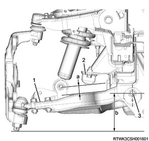
Legend
- Lower link
- Bumper rubber
- Rear cam bolt center
Legend
a. Buffer clearance
b. Trim height
| Buffer clearance (Reference value) |
26 mm { 1.02 in } |
| Trim height (Reference value) |
140 mm { 5.5 in } |
2WD (High ride suspension specifications), 4WD
Legend
- Lower link
- Bumper rubber
- Rear cam bolt center
Legend
a. Buffer clearance
b. Trim height
4. Adjustment of the trim height
1) Loosen the cam bolt lock nut.
2) Rotate the cam bolt and adjust the buffer clearance and trim height.
| Buffer clearance (Reference value) |
25.9 mm { 1.02 in } |
| Trim height (Reference value) |
119 mm { 4.7 in } |
2WD (Except high ride suspension specifications)
Legend
- Lower link
- Buffer clearance
- Rear cam bolt center
Legend
a. Buffer clearance
b. Trim height
| Buffer clearance (Reference value) |
26 mm { 1.02 in } |
| Trim height (Reference value) |
140 mm { 5.5 in } |
2WD (High ride suspension specifications), 4WD
Legend
- Lower link
- Buffer clearance
- Bumper rubber
- Rear cam bolt center
- Trim height
Legend
a. Buffer clearance
b. Trim height
3) After adjusting the buffer clearance and trim height, tighten the lock nut to secure the lower link.
Tightening torque: 186 N・m { 19.0 kgf・m / 137 lb・ft }
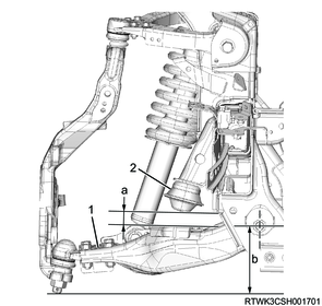
5. Caster and camber adjustment
1) Park the vehicle on a level surface.
2) Inspect the wheel alignment using an alignment device.
Note
- For the use of the alignment devices, follow the manufacturer's owners manuals.
3) Loosen the lower link cam bolt nut as necessary.
4) Adjust the caster and camber.
An adjust cam is fitted to either front or back end of the front suspension lower link. This allows for simultaneous adjustment of camber and caster angles.

Legend
- Lower link (RH)
- Plus (+) direction (The lower link will move outward.)
- Minus (-) direction (The lower link will move inward.)
- Lower link (LH)
- Plus (+) direction (The lower link will move outward.)
- Minus (-) direction (The lower link will move inward.)
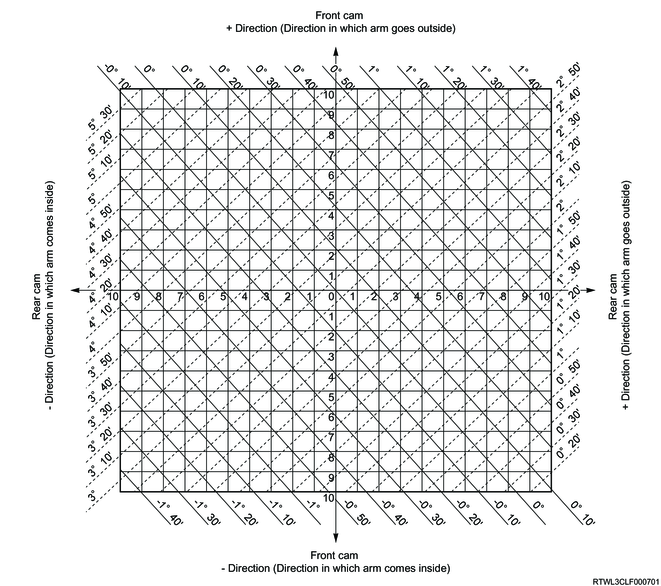
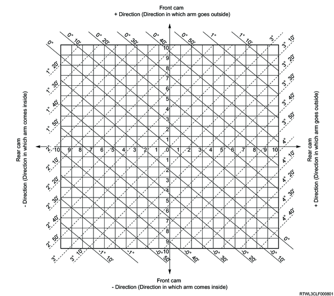
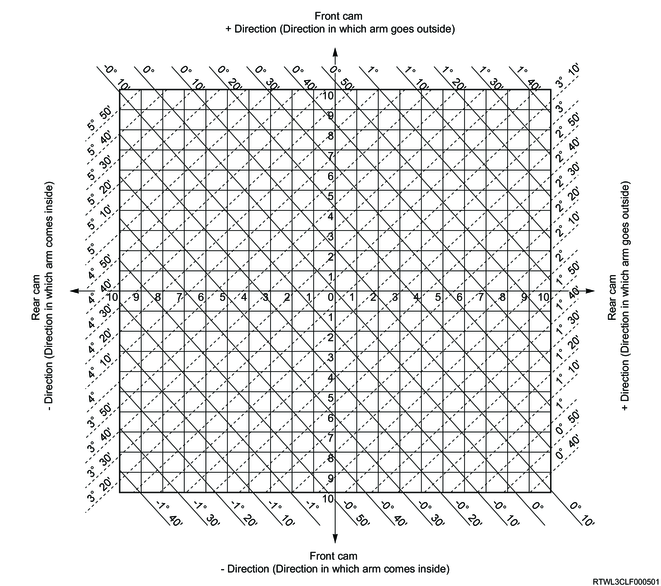
The following illustration describes the camber and caster adjustment procedure.
2WD except high ride suspension (Cab-chassis specifications)
2WD high ride suspension and 4WD (Cab-chassis specifications)
2WD except high ride suspension (Except cab-chassis specifications)
2WD high ride suspension and 4WD (Except cab-chassis specifications)
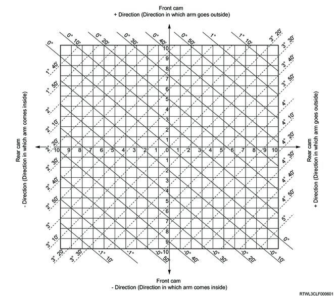
As an adjustment example, measurement values from the following table are used here.
| Camber angle |
1°10' |
| Caster angle |
3°10' |
| Measurement items |
Standard value |
Remarks |
|
| Camber angle |
0°±30' |
Equally in right and left sides in 30' range |
|
| Caster angle |
Cab-chassis specifications |
2°55' ± 45' |
|
| Except cab-chassis specifications |
3°15' ± 45' |
||
| Kingpin inclination angle |
12°30'±30' |
- |
|
| Measurement items |
Standard value |
Remarks |
|
| Camber angle |
0°±30' |
Equally in right and left sides in 30' range |
|
| Caster angle |
Cab-chassis specifications |
3°00' ± 45' |
|
| Except cab-chassis specifications |
3°20'±45' |
||
| Kingpin inclination angle |
12°30'±30' |
- |
|
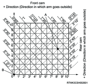
Mark "A" at the intersection of camber measured angle value (solid line) and caster measured angle value (dotted line).

Mark "B" at the intersection of camber standard angle value (solid line) and caster standard angle value (dotted line).
Vertical distance between points A and B shows adjustment required for front cam.
Horizontal distance between points A and B shows adjustment required for rear cam.
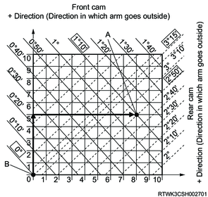
In this case, the front cam may move in the plus direction 5 increments, and the rear cam may move in the plus direction 8 increments.
5) Final tighten the lower link cam bolt nut.
Tightening torque: 186 N・m { 19.0 kgf・m / 137 lb・ft }
6. Toe-in measurement
Toe-in measurement and adjustment should be performed with the vehicle parked on a flat plate.
If it is difficult to park on a flat plate, perform with the vehicle parked on a level floor.
1) Set the front wheel to the position for advancing straight forward.
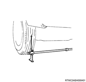
2) Place the tip of the toe-in gauge in the center of the tire treads at a height equal to the center of the wheel shaft on the back of the left and right front wheels, and make a mark.
3) Measure distance 2 between the marks on the back of the front wheels.
4) Rotate the front wheels 180°.
5) Measure distance 1 between the left and right marks on the front of the vehicle.
6) Obtain the toe-in from the measured values.
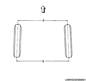
Legend
a. Distance 1
b. Distance 2
| Standard value |
| 0 ± 2 mm {0 ± 0.08 in} |
7. Toe-in adjustment
1) Loosen the tie rod lock nut.
2) Rotate the tie rod to adjust the toe-in.
To keep the steering wheel in the center position, adjust by rotating both of the left and right tie rods only the same amount.
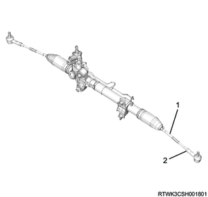
Legend
- Tie rod
- Lock nut
| Standard value |
| 0 ± 2 mm {0 ± 0.08 in} |
3) After adjusting the toe-in, tighten the lock nut to secure the tie rod.
Tightening torque: 98 N・m { 10.0 kgf・m / 72 lb・ft }
8. Wheel steering angle adjustment
1) Adjust the wheel steering angle.
The wheel steering angle is not adjustable, but if there is significant left/right difference, inspect the suspension arm, knuckle, tie rod, etc., for damage.
If an abnormal condition is not found as a result of inspection, in the same way as the toe-in adjustment, turn the left and right tie rods the same amount to make the left and right steering angles roughly the same.
| Standard value |
| Inside 39.0° Outside 35.0° |
| Standard value |
| Inside 37.7° Outside 33.9° |