1. Component views
Starter motor
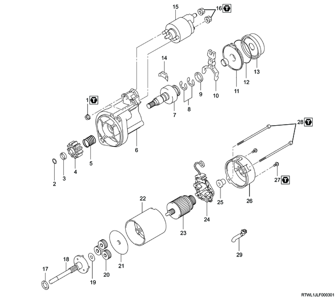
Part name
- Nut
- Snap ring
- Nut
- Pinion
- Spring
- Housing
- Clutch
- Washer
- Washer
- Shift lever
- Bearing
- Starter spring
- Internal gear
- Seal
- Magnetic switch
- Nut
- Washer
- Clutch shaft
- Washer
- Planetary gear
- Plate
- Yoke
- Armature
- Brush holder
- Bearing
- Rear cover
- Screw
- Through bolt
- Drain bushing
Tightening torque
1: 7.5 N・m { 0.8 kgf・m / 66 lb・in }
16: 6.5 N・m { 0.7 kgf・m / 58 lb・in }
27: 2.0 N・m { 0.2 kgf・m / 18 lb・in }
28: 6.0 N・m { 0.6 kgf・m / 53 lb・in }
2. Starter motor preparation
1. Diagnosis before disassembly
Perform the following tests before disassembling the starter motor for repair.
Caution
- Do not ever operate the starter motor for more than 30 seconds at a time.
- Allow the starter motor to cool for at least 2 minutes before operating again.
2. Starter motor test
1) With the starter motor removed from the engine, rotate the pinion gear on the spline shaft and check whether the pinion gear moves freely.
2) Rotate the pinion gear with a screwdriver and check whether the armature rotates freely.
Note
- Keep in mind that there is more drag with the gear reduction starter motor.
- A tight bearing, a bent armature, a thick grease, or a loose pole shoe causes a high level of drag.
- If the drag is low with no sounds of grinding or jamming, perform the no-load test for the motor before disassembly.
3) Before performing the no-load test of the starter, perform the operation test of the solenoid as follows.
- Connect the 12 V battery power supply and turn the switch ON.
- Pull in the magnetic switch as indicated by the pinion gear moving to the maximum travel position.
Note
- If the magnetic switch does not operate properly, repair the magnetic switch before performing the no-load test on the starter.
3. No-load test
1) Secure the starter in a vise.
Caution
- Do not clamp around the magnetic switch.
2) Check that the battery is fully charged (12 V), and then connect the starter motor and an ammeter in series.
3) After the pinion clutch gear was engaged, check the movement of the starter.
Caution
- The starter should be 11.5 V, 150 A or less. The speed of the pinion gear indicated on the tachometer should be 2560 r/min or more.
Note
- It is not necessary to obtain the exact specified voltage because a good reading can be made by understanding that if the voltage is slightly higher, the speed per minute will be slightly higher, with the current remaining basically unchanged. However, if the exact voltage is desired, the voltage can be reduced to the specified value by using a carbon pile connected to the battery.
- If 2 or more 12 V batteries are used in series, connect the carbon pile to only 1 of the 12 V batteries.
4. No-load test result
Rated current draw and no-load speed indicates the normal state of the starter motor.
Low free speed and high current draw indicates the following.
- Excessive friction
- A tight, dirty, or worn bearing, a bent armature, or a loose pole shoe, which could cause a drag of the armature
- Shorted armature
- Grounded armature or field
Note
- A short circuit in the armature can be further checked on the growler after disassembly.
- Further check the grounded armature or field after disassembly.
The starter motor does not rotate. The ammeter indicates a high current flow. These indicate the following.
- Directly grounded terminal or field
- Stuck bearing
Note
- A stuck bearing should be checked by rotating the armature manually.
The starter motor does not rotate. The ammeter indicates no current flow. These indicate the following.
- Open circuit in field circuit
- Open armature coil
- Broken brush spring, worn brush, high insulation between the commutator bars, or other factors that prevent good contact between the brush and the commutator
Note
- An open circuit in the field circuit can be checked by inspecting the internal connection after disassembly and tracing the circuit with a test light.
- If there is an open armature coil, disassemble it and inspect the commutator for heavily burned bars.
Low no-load speed and low current draw indicates high internal resistance due to the following factors.
- Poor connection
- Defective lead wire
- Dirty commutator
- Factors listed for the cases where the starter motor does not rotate
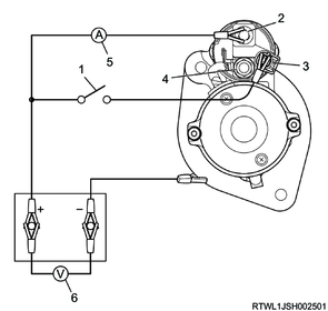
Legend
- Switch
- Solenoid battery terminal
- Solenoid start terminal
- Solenoid motor terminal
- Ammeter
- Voltmeter
High free speed and high current draw indicate a short circuit in the field.
Note
- If a short circuit in the field is suspected, replace the field coil and check whether the performance is improved.
3. Starter motor disassembly
1) Clean the outside of the starter motor and place alignment marks on the housing and magnetic switch.
2) Remove the nut and connecting lead portion of the brush holder.
3) Remove the magnetic switch.
4) Remove the through bolts.
5) Remove the screw, rear cover, and bearing.
6) Remove the brush holder.
7) Remove the armature.
8) Remove the yoke and plate.
9) Remove the clutch shaft from the housing and shift lever.
10) Remove the planetary gear.
11) Remove the snap ring, nut, and clutch.