1. Component views
Camshaft
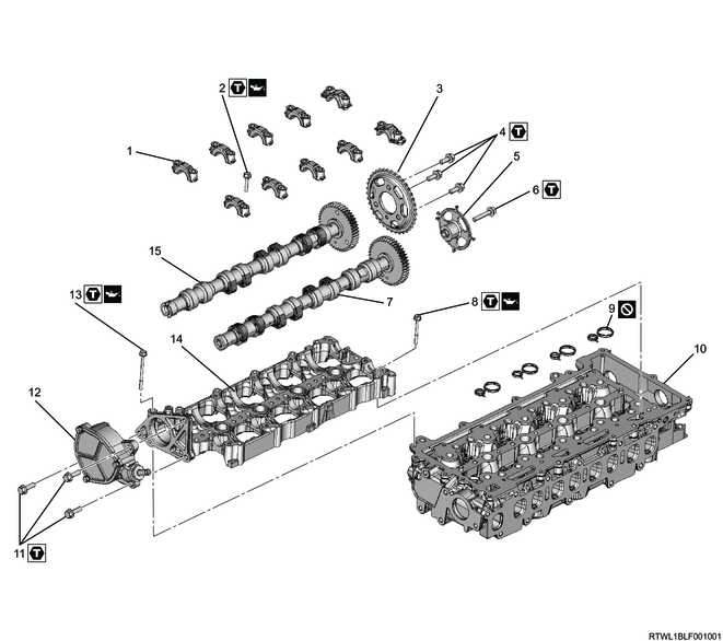
Part name
- Camshaft cap
- Bolt
- Camshaft sprocket
- Bolt
- Cam angle sensor rotor
- Bolt
- Inlet camshaft
- Bolt
- Gasket
- Cylinder head
- Bolt
- Vacuum pump
- Bolt
- Camshaft carrier
- Exhaust camshaft
Tightening torque
2: 7.0 N・m { 0.7 kgf・m / 62 lb・in }
4: 25 N・m { 2.5 kgf・m / 18 lb・ft }
6: 25 N・m { 2.5 kgf・m / 18 lb・ft }
8: 7.0 N・m { 0.7 kgf・m / 62 lb・in }
11: 25 N・m { 2.5 kgf・m / 18 lb・ft }
13: 7.0 N・m { 0.7 kgf・m / 62 lb・in }
2. Camshaft installation
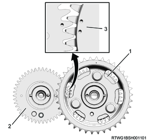
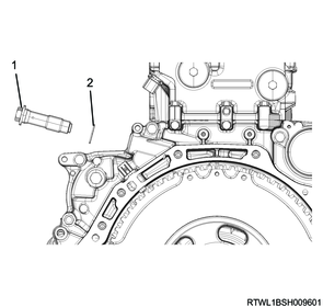
1) Install the camshaft sprocket to the exhaust camshaft.
Note
- Install so that it is aligned with the pin of the exhaust camshaft gear end surface.
- Referring to the diagram, secure the section indicated by the arrow.
Tightening torque: 25 N・m { 2.5 kgf・m / 18 lb・ft }
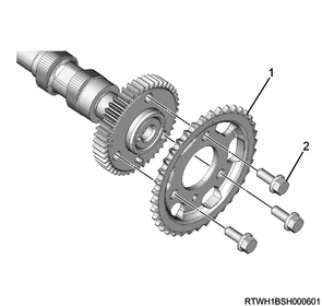
Legend
- Camshaft sprocket
- M8 bolt
Fixing position
2) Apply engine oil to the camshaft journal and No. 5 journal thrust receiving section.
3) Install the camshaft to the camshaft carrier with the inlet camshaft and exhaust camshaft markings upward.
Note
- Check that the inlet camshaft gear and the exhaust camshaft gear timing marks are aligned.
Legend
- Exhaust camshaft gear
- Inlet camshaft gear
- Timing mark
4) Apply engine oil to the following parts.
- Camshaft cap sliding surface
- Camshaft journal
- Threaded portion and seating surface of bolts
5) Install the camshaft cap to the camshaft carrier.
Note
- Check the journal positions marked on the camshaft caps and install.
Tightening torque: 7.0 N・m { 0.7 kgf・m / 62 lb・in }

6) Remove the M5 lock bolt from the inlet camshaft gear.
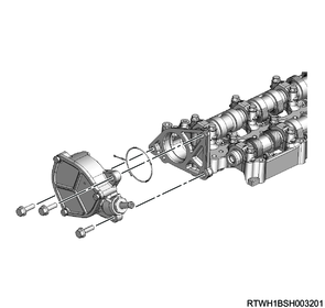
3. Vacuum pump installation
1) Install the vacuum pump to the camshaft carrier.
Tightening torque: 25 N・m { 2.5 kgf・m / 18 lb・ft }
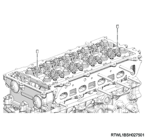
4. Camshaft carrier installation
1) Install the dowel pin to the cylinder head.
Note
- Insert until full contact is made.
2) Check that the inlet camshaft and the exhaust camshaft notches are aligned with the camshaft cap alignment marks.

Legend
- Alignment mark
- Notch
3) Confirm that the 4 gaskets are installed to the lower surface of the camshaft carrier.
4) Referring to the diagram, apply ThreeBond 1207B to the cylinder head.
Caution
- Within 5 minutes of applying the liquid gasket, install the camshaft carrier.
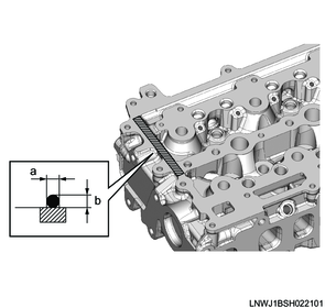
Standard value
a: 2.0 to 3.0 mm { 0.079 to 0.118 in } Bead width
b: 2.0 to 3.0 mm { 0.079 to 0.118 in } Bead height
5) Apply engine oil to the threaded portions and seating surfaces of the bolts.
6) Temporarily tighten the camshaft carrier to the cylinder head in the order shown in the diagram.
Note
- Check the rocker arm for position misalignment before and after installation.

7) Check that the camshaft carrier has been seated on the cylinder head.
8) Final tighten the camshaft carrier to the cylinder head in the order shown in the diagram.
Tightening torque: 7.0 N・m { 0.7 kgf・m / 62 lb・in }
9) Connect the vacuum hose to the vacuum pump.
10) Align the paint markings and install the timing chain to the camshaft sprocket.
Note
- Align to the marked position before removal.

Legend
- Camshaft sprocket
- Timing chain
- Paint marking
11) Install the timing chain tensioner and gasket to the flywheel housing.
Caution
- Do not reuse the gasket.
Tightening torque: 70 N・m { 7.1 kgf・m / 52 lb・ft }
Legend
- Timing chain tensioner
- Gasket
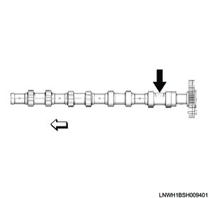
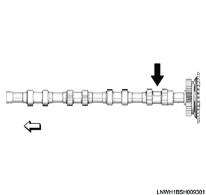
12) Install the cam angle sensor rotor to the inlet camshaft.
Note
- Install by aligning with the positioning pin.
- Referring to the diagram, secure the section indicated by the arrow.
Tightening torque: 25 N・m { 2.5 kgf・m / 18 lb・ft }
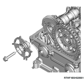
Fixing position