1. Component views
Starter motor
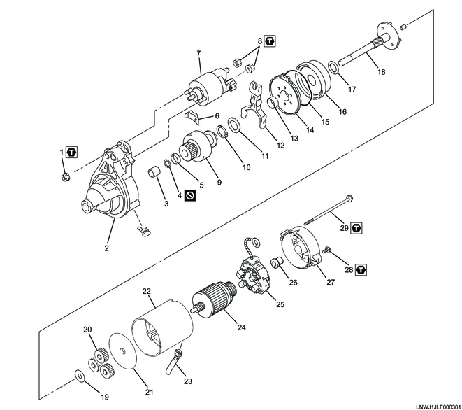
Part name
- Nut
- Housing
- Bearing
- Snap ring
- Pinion stopper
- Dust cover
- Magnetic switch
- Nut
- Pinion and overrunning clutch
- Snap ring
- Washer
- Shift lever
- Bearing
- Shock absorber
- Starter spring
- Internal gear
- Washer
- Clutch shaft
- Washer
- Planetary gear
- Plate
- Yoke
- M-terminal lead wire
- Armature
- Brush holder
- Bearing
- Rear cover
- Screw
- Through bolt
Tightening torque
1: 7.5 N・m { 0.76 kgf・m / 66.4 lb・in }
8: 10.0 N・m { 1.0 kgf・m / 89 lb・in }
28: 1.5 N・m { 0.15 kgf・m / 13.3 lb・in }
29: 5.5 N・m { 0.56 kgf・m / 48.7 lb・in }
2. Starter motor reassembly
1) Install the following parts to the clutch shaft.
- Bearing
- Snap ring
- Pinion stopper
- Pinion and overrunning clutch
- Starter spring
- Internal gear
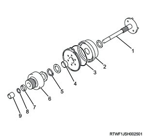
Legend
- Clutch shaft
- Internal gear
- Starter spring
- Bearing
- Snap ring
- Pinion and overrunning clutch
- Pinion stopper
- Snap ring
- Bearing
2) Install the planetary gear to the clutch shaft.
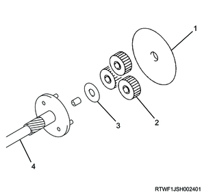
Legend
- Plate
- Planetary gear
- Washer
- Clutch shaft
3) Install the shift lever to the housing.

Legend
- Housing
- Shift lever
4) Install the pinion, overrunning clutch, and the clutch shaft as a set to the housing.
5) Install the yoke and plate to the housing.
6) Install the armature to the housing.
Legend
- Yoke
- Alignment mark
- Armature
7) Install the 4 brushes to the brush holder.
8) Prepare the brush holder.
Note
- If reusing a brush holder, insert the brush into the brush holder with a collar that is the same diameter as the commutator.
Caution
- Do not damage the brush.
Legend
- M-terminal lead wire
- Rubber seal
- Brush holder
- Collar
- Holder plate
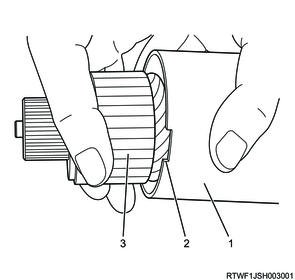
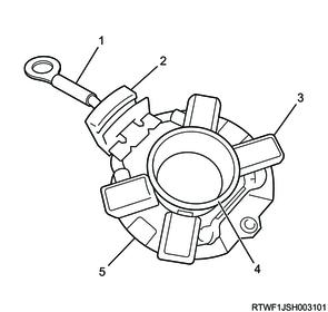
9) Referring to the diagram, install the brush holder to the commutator while gradually pulling out the collar.
Caution
- Do not damage the commutator surface.
- Insert it slowly until the collar comes out completely.
Legend
- Yoke
- Commutator
- Brush holder
- Collar

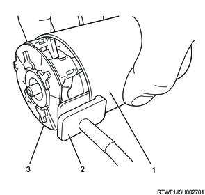
Legend
- Yoke
- Brush holder
- Collar
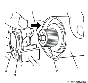
10) Align the rubber seal with the alignment mark.
Note
- Firmly push the rubber seal into the alignment mark.
Legend
- Yoke
- Rubber seal
- Brush holder
11) Install the rear cover to the yoke.
Tightening torque: 5.5 N・m { 0.56 kgf・m / 48.7 lb・in } Through bolt
Tightening torque: 1.5 N・m { 0.15 kgf・m / 13.3 lb・in } Screw
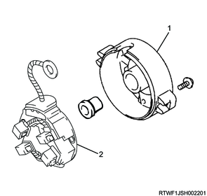
Legend
- Rear cover
- Brush holder
12) Install the dust cover to the housing.
13) Install the magnetic switch to the housing.
Note
- Align the marking to install.
Tightening torque: 7.5 N・m { 0.76 kgf・m / 66.4 lb・in }
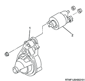
Legend
- Housing
- Magnetic switch
14) Connect the lead wire of the magnetic switch to the magnetic switch M-terminal.
Tightening torque: 10 N・m { 1.0 kgf・m / 89 lb・in }
1. Pull-in test
Caution
- Be sure to perform the test with the starter motor fully assembled.
- The yoke lead wire must not be connected to the M-terminal.
- To prevent coil seizure, complete the test as quickly as possible.
- Complete the test within 3 to 5 seconds.
1) Connect the battery negative terminal to the starter motor and M-terminal.
2) Connect the battery positive terminal to the S-terminal.
Note
- If current is flowing from the battery positive terminal to the S-terminal, the pinion should pop out.
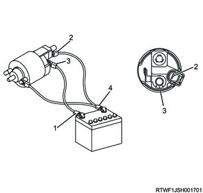
Legend
- Positive terminal
- S-terminal
- M-terminal
- Negative terminal
2. Hold-in test
1) Disconnect the M-terminal lead wire from the M-terminal.
Note
- The pinion should continue popping out.

Legend
- Positive terminal
- Plunger
- S-terminal
- M-terminal
- Negative terminal
3. Return test
1) Disconnect the battery positive lead of the S-terminal from the S-terminal.
Note
- The pinion should be returned to the specified position.
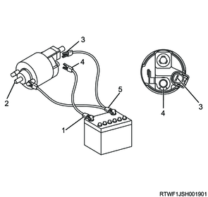
Legend
- Positive terminal
- Plunger
- S-terminal
- M-terminal
- Negative terminal
4. No-load test
1) Referring to the diagram, connect the starter to the battery.
Caution
- Use a sufficiently thick electric wire, and securely tighten the connection.
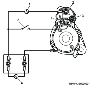
Legend
- Ammeter
- B-terminal
- S-terminal
- M-terminal
- Switch
- Voltmeter
2) Close the switch, and check the current and voltage.
Caution
- If the reading is outside the standard range, disassemble and inspect once again.
Standard: 11.5 V
Standard: 90 A or less
Standard: 2,600 rpm or more