1. Component views
Selector lever
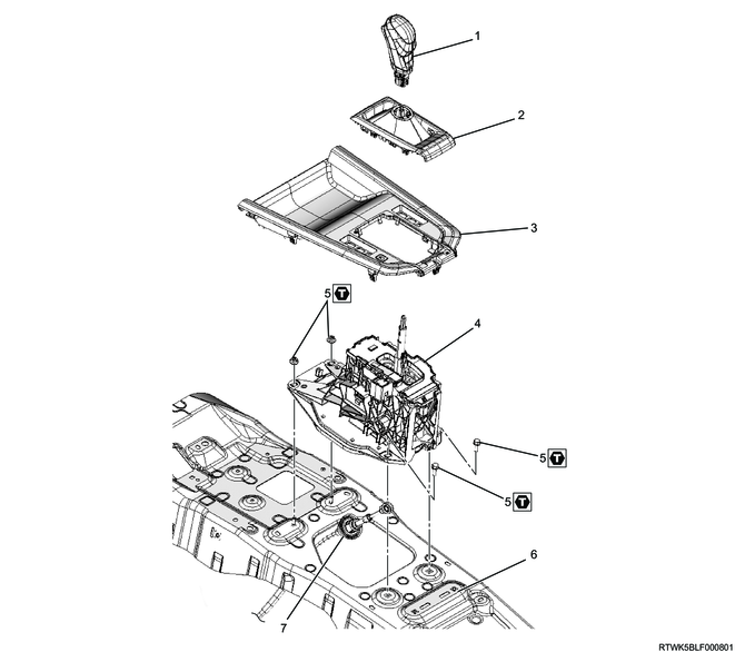
Part name
- Selector lever knob
- Selector boot
- Shift console cover
- Selector lever
- Bolt and nut
- Floor panel
- Automatic transmission control cable
Tightening torque
5: 7 N・m { 0.7 kgf・m / 62 lb・in }
2. Selector lever installation
1) Before installing the selector lever, be sure to install the automatic transmission control cable on the transmission side with the adjuster of the cable unlock.
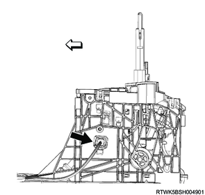
2) Connect the automatic transmission control cable to the selector lever.
Note
- Securely install in the correct way as shown in the diagram below.
Correct installation motion

Incorrect installation motion
Note
- Install the selector lever to the floor panel following the tightening sequence below.
3) Temporarily tighten the front nuts.
4) Temporarily tighten the rear bolts.
5) Tighten the front nuts to the specified torque.
6) Tighten the rear bolts to the specified torque.
Tightening torque: 7 N・m { 0.7 kgf・m / 62 lb・in }
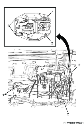
Legend
- Nuts
- Bolts
7) Connect the harness connector to the selector lever.

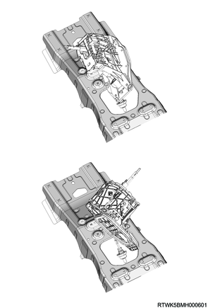
3. Rear ventilation duct installation
1) Install the rear ventilation duct to the floor panel.
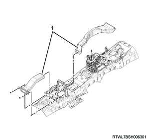
Legend
- Rear ventilation duct
4. Shift console cover installation
1) Install the selector boot to the shift console cover.
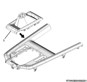
Legend
- Selector boot
5. Console box installation
6. Automatic transmission control cable adjustment
1) Check that the selector lever and transmission are in N position.
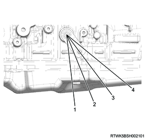
Legend
- P
- R
- N
- D
2) Lock the automatic transmission cable adjuster.
Note
- Insert the lock piece to the adjuster.
- Slide the cover on the adjuster and secure lock piece.
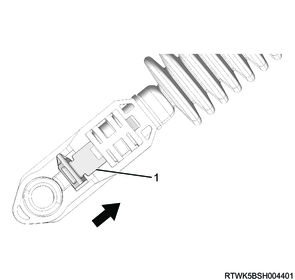
Legend
- Cover
3) Press the select lever knob button 5 times, and then check that the select lever moves to each position smoothly.
Note
- Check on ACC condition or Engine start condition with the brake applied.
4) Check that the shift position indicated on the meter cluster and the actual shift position are matched.
7. Preliminary and post procedures
1. Post procedures
1) Connect the battery cable to the battery negative terminal.
2) Referring to the following, perform the setting of the front door power window switch with AUTO UP/AUTO DOWN function.
Refer to "9.Body, Cab, Accessories 9T.Glass, Windows, Mirrors front door power window switch setting".
3) Close the engine hood.