1. Function, structure, operation of transmission, transaxle
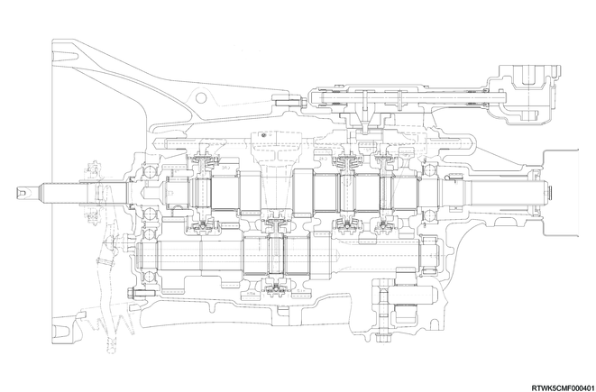
Cross-sectional drawing of MVL6Y transmission (RZ4E, 2WD models)
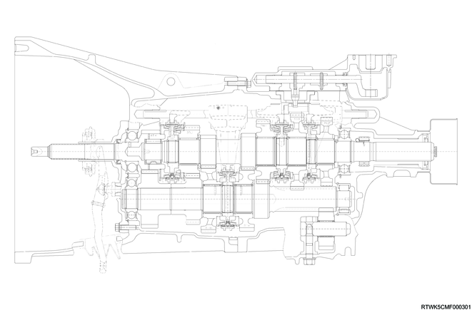
Cross-sectional drawing of MVL6S transmission (4JJ3, 2WD models)
Cross-sectional drawing of MVL6Y transmission (RZ4E, 4WD models)

Cross-sectional drawing of MVL6S transmission (4JJ3, 4WD models)
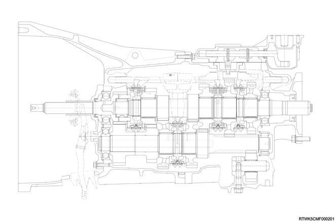
MVL6S and MVL6Y transmissions are constant-mesh type transmissions that synchronize at all speeds. This transmission is designed to achieve operating force reduction and quietness.
The main components of the transmission include a clutch housing, rear case, and gear. The transmission control box is built into the transmission.
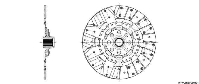
Cross-sectional drawing of the clutch
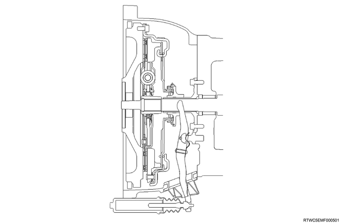
The clutch assembly consists of a clutch pressure plate, clutch cover, diaphragm spring pivot pin, and clutch disc.
The clutch pedal is connected to the release bearing assembly via the shift fork.
The clutch disc is installed between the flywheel and the clutch pressure plate.
This transmission adopts a push-type clutch.
When the clutch pedal is depressed, the shift fork moves toward the release bearing assembly.
The release bearing assembly causes the diaphragm to forcibly overcome the force of the spring, and the clutch disc separates from the flywheel and clutch pressure plate to disengage the clutch.
Master cylinder (RZ4E)

Master cylinder (4JJ3)
The master cylinder converts mechanical energy into hydraulic energy.
When the clutch pedal is depressed, the push rod moves relative to the piston, and closes the return port.
Clutch fluid is forcibly discharged from the master cylinder.
When the clutch pedal is released, the reaction force of the diaphragm spring causes the piston to return to the original position.
The return port opens, and the clutch fluid returns into the fluid reservoir.
When the clutch pedal is quickly released, the fluid pressure on the compression chamber side becomes lower than the fluid pressure on the push rod side.
As a result, the fluid pressure on the push rod side passes through the port within the piston head, and abruptly flows to the compression chamber side.
This results in an equal pressure at both sides of the piston.
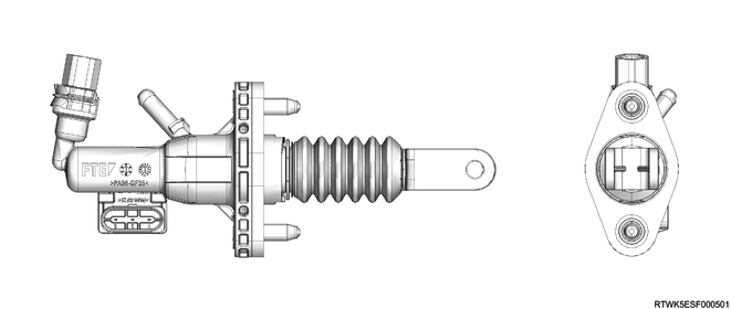
Cross-sectional drawing of slave cylinder (RZ4E)

Cross-sectional drawing of slave cylinder (4JJ3)

The slave cylinder converts hydraulic energy into mechanical energy.
The oil pressure supplied from the master cylinder moves the slave cylinder, and the shift fork is activated.
The mechanical energy generated by the slave cylinder is directly proportional to the diameters of the master cylinder and slave cylinder.
The air bleeder screw is equipped for bleeding air from the slave cylinder.
If the clutch abruptly engages at "Low" or "Reverse", the clutch damper valve lowers the return speed of the clutch fluid, and reduces the shock torque sent to the drive train.
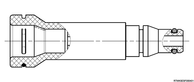
Cross-sectional drawing of the oil pressure damper cylinder

The oil pressure damper cylinder is installed between the master cylinder and the slave cylinder to smoothen clutch pedal feeling fluctuations.
Cross-sectional drawing of orifice valve (4JJ3 except dual mass flywheel specifications)
The orifice valve reduces shock input to the drive system generated by rapid engagement of the clutch pedal, such as sideways disengagement of the clutch pedal, by narrowing the clutch hydraulic pressure path.
Damper (4JJ3 dual mass flywheel specifications)

The damper is installed between the master cylinder and the slave cylinder to smoothen clutch pedal feeling fluctuations.
Cross-sectional drawing of pressure plate (RZ4E)

Cross-sectional drawing of pressure plate (4JJ3 except dual mass flywheel specifications)

Cross-sectional drawing of pressure plate (4JJ3 dual mass flywheel specifications)
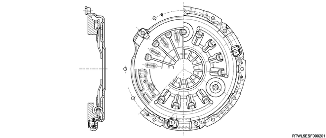
The pressure plate assembly consists of a pressure plate with diaphragm spring.
When the clutch pedal is operated, the pressure plate moves in the axial direction and engages or disengages the clutch.
Cross-sectional drawing of clutch disc (Except dual mass flywheel specifications)
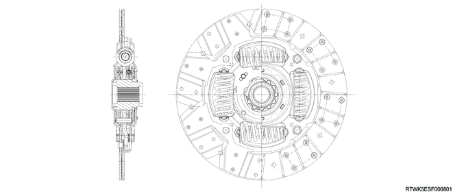
Cross-sectional drawing of clutch disc (Dual mass flywheel specifications)
The clutch disc consists of the plate and facing.
Except models with dual mass flywheel specifications, the plate consists of the clutch center, cushioning plate, and torsion spring.
For models with dual mass flywheel specifications, the plate consists of the clutch center and cushioning plate.
The facing is secured with rivets to both sides of the cushioning plate.
The cushioning plate minimizes wear and vibration of the clutch contact surface, which prolongs the service life.