1. Wiring repair precautions
Warning
- Do not perform battery cable connection repair, because this may lead to a vehicle fire.
- Because vehicle fires can be caused by electrical wire connections when wires twist together, or by insufficient insulation processing, be sure to follow the instructions in the workshop manual to perform appropriate connections and sound insulation processing.
- Because using a fuse with a capacity other than the specified capacity may lead to a vehicle fire, make sure to use a fuse with the specified capacity.
- Do not modify or repair the aluminum wire. (If there is an abnormal condition with the wire, be sure to replace the harness with a new one.)
Caution
- When repairing the wiring, start work after turning the ignition switch OFF and verifying that the lighting switches, etc., are OFF.
- After turning OFF the ignition switch (power mode for models with passive entry and start system), do not disconnect the battery cable within 3 minutes.
- If the battery cable is disconnected within 3 minutes, the vehicle electronic control system may malfunction.
- Disconnect the battery cable from the battery negative terminal.
- For the battery cable, connect the battery negative terminal after all work is complete.
- If the fuse blows out, make sure to replace it with a non-defective fuse of the same capacity after identifying the cause of the blowout.
- Connecting the terminal poles and connectors incorrectly may result in component malfunction and damage, so be sure to connect them correctly.
- Do not perform connection repairs in areas with bending or runout, or areas that may be at a high temperature.
- Do not perform connection processing in areas that move relative to one another, such as the cab-to-frame and engine- or transmission-to-frame areas, etc.
- If wiring repair is needed on parts that move relative to each other, replace the whole span of the routing section with extension wiring, and perform connection processing to the parts outside of the span of the routing section.
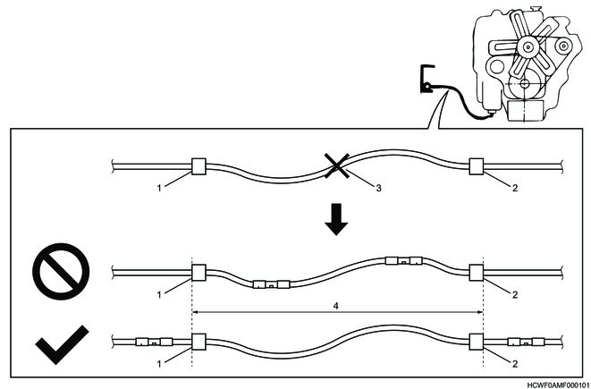
Legend
- Fixed to non-moving parts (Fixture on the frame, etc.)
- Fixed to moving parts (Fixture on the engine, etc.)
- Damaged components
- Span of the routing section
Caution
- When repairing the wiring, take care not to damage nearby electrical wires and other components.
- When performing work, make sure to return the removed terminals, connectors, wiring, and clips to their original positions.
- If the clip used for fastening the harness is damaged, replace it with a new one.
- If the rubber or plastic coating of a metal clip peels off or has perforations or cracking, replace the clip with a new one.
2. How to install ground wiring
Caution
- Because the existing ground point is set in a position that guarantees operation of the various devices, do not move it.
- For the ground wire, make sure to use a round terminal and securely fasten the wire to the frame and panel using the ground bolts.
- Do not tighten the extension ground wire together with the ground point, because looseness or poor connections may result.
- If the ground bolt is damaged, replace it with the specified ground bolt.
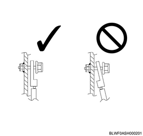
- If changing the ground point to a weld nut from the tap hole of the frame, use a ground bolt with a lock section long enough to twist more than 2 threads around the threaded portion of the weld nut.
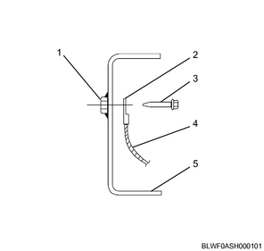
Legend
- Weld nut
- Round terminal
- Ground bolt
- Ground wire
- Side member
3. Ground bolt list
1. Ground bolt
Ground bolt with spring washer
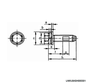
Dimensions
a. T2
b. T1
c. φD2
d. φD1
e. a
f. La
g. d
h. L
Ground bolt without spring washer
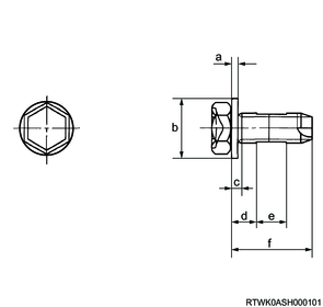
Dimensions
a. T2
b. φD2
c. a
d. La
e. d
f. L
| Part number |
Nominal diameter |
Pitch |
Maximum (a) |
Stem length (L) |
Spring washer (T1 x φD1) |
Plain washer (T2 x φD2) |
Lock length (d) |
Lock position (La) |
| 898164-8360 |
M6 |
1 |
2.6 |
14 |
- |
1.6 x 12 |
4 |
5 |
| 897086-8220 |
3.9 |
14 |
1.2 x 11.3 |
3.5 |
6 |
|||
| 897086-8230 |
5.4 |
16 |
4 |
7.5 |
||||
| 897086-8240 |
5.4 |
20 |
10 |
|||||
| 897087-2010 |
5.4 |
25 |
16.5 |
|||||
| 897087-6170 |
5.4 |
40 |
31 |
|||||
| 897119-4790 |
3.9 |
14 |
6 |
|||||
| 897206-4070 |
3.9 |
14 |
3.5 |
6 |
||||
| 898164-8370 |
M8 |
1.25 |
3 |
14 |
- |
1.6 x 16 |
4 |
5 |
| 898141-2550 |
3 |
18.5 |
- |
6.5 |
6 |
|||
| 897086-8250 |
6.5 |
20 |
1.6 x 14.3 |
4 |
10 |
|||
| 898141-2561 |
3 |
22 |
- |
8 |
7 |
|||
| 897087-0550 |
4.7 |
16 |
1.6 x 14.3 |
4 |
6 |
|||
| 897087-2030 |
6.5 |
25 |
15 |
|||||
| 897087-2040 |
6.5 |
30 |
20 |
|||||
| 897264-7660 |
2 |
23 |
- |
With φ16 flange |
5 |
4 |
||
| 898164-8380 |
M10 |
1.25 |
4.5 |
20 |
- |
2 x 20 |
6.5 |
6 |
| 897087-2050 |
5.9 |
25 |
1.8 x 17.4 |
5 |
10 |
|||
| 897087-2060 |
7.2 |
30 |
17.5 |
| Nominal diameter |
Tightening torque |
| M6 |
5.8 to 9.8 N⋅m {0.6 to 1.0 kgf⋅m / 51 to 87 lb⋅in} |
| M8 |
13.7 to 23.5 N⋅m {1.4 to 2.4 kgf⋅m / 121 to 208 lb⋅in} |
| M10 |
34.3 to 46.1 N⋅m {3.5 to 4.7 kgf⋅m / 25 to 34 lb⋅ft} |
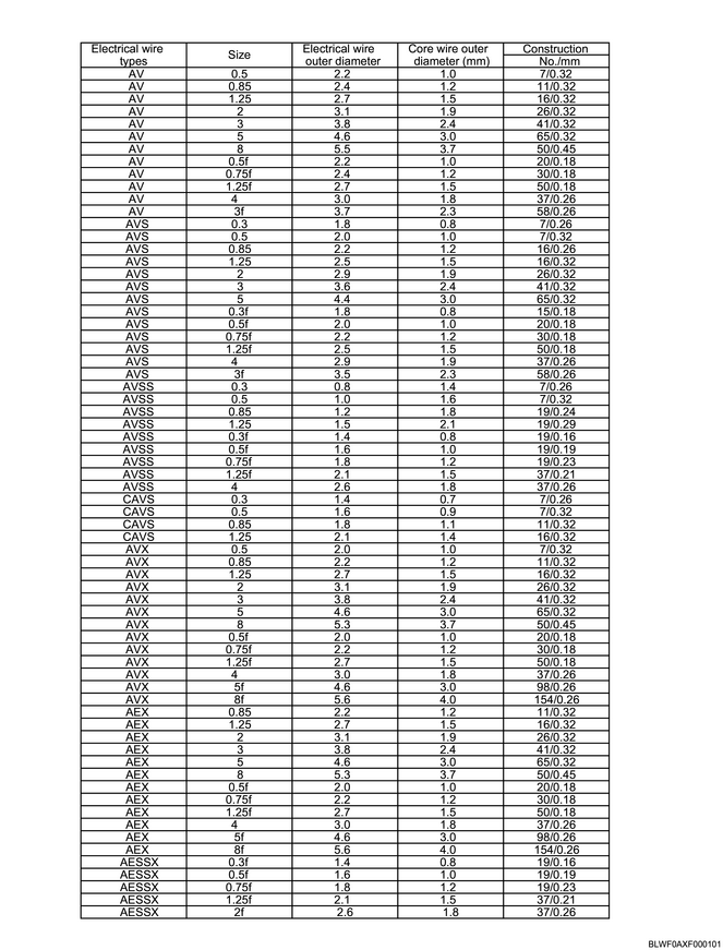
4. Type and size of wire
1. Electrical wire type
| Recommended electrical wire type |
Purpose |
| AV wire |
General components: Components other than high temperature components |
| AVS wire |
|
| AVSS wire |
|
| CAVS wire |
|
| AVX wire |
High temperature components: Engine, exhaust pipe heat source surroundings |
| AEX wire |
|
| AESSX wire |
2. Electrical wire size
Note
- The electrical wire size is expressed as the cross-sectional area of the core wire (copper wire).
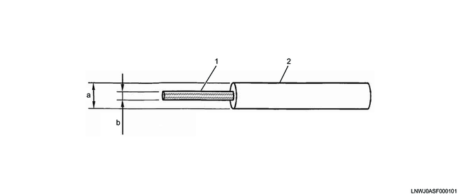
Legend
- Core wire
- Electrical wire
Dimensions
a. Electrical wire outer diameter
b. Core wire outer diameter
5. Repair method of damaged wire
1. Electrical wiring connection (joining)
If repairing a damaged circuit or reconstructing a damaged circuit (separate wiring), cut off the damaged part of the circuit and connect it with the electrical extension wire.
1) When connecting wires using the specified joint terminal, prepare an electrical extension wire the same length as the cut electrical wire.
Note
- If there are recommended dimensions for the joint terminal being used, add the length of 2 locations to that length.
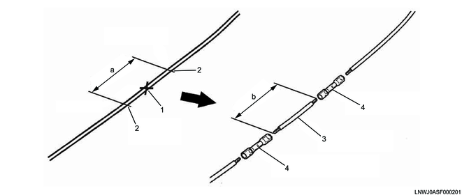
Legend
- Damaged components
- Cut location
- Electrical extension wire
- Joint terminal
Dimensions
a. Length of the cut location
b. Length of the electrical extension wire
Note
- When connecting 4 electrical wires or more, connect them by sliding them back and forth without gathering them into the same place.
- Even when connecting 3 electrical wires or less, connect them by sliding them back and forth even if they do not fit into the protective material.
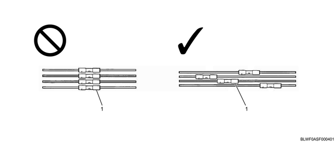
Legend
- Joint terminal
2) If connecting wires using soldering or joint connectors other than those specified, etc., prepare a length of the electrical extension wire equal to the sum of the lengths of the 2 electrical wire strips and the length of the cut electrical wire.
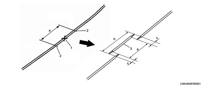
Legend
- Damaged components
- Cut location
- Electrical extension wire
Dimensions
a. Length of the wire to be cut
b. Length of the electrical extension wire
c. Length of the electrical wire strip
2. Repair method for damaged connectors and components near the connectors
If the connectors or the components near the connectors are damaged, prepare a replacement connector and perform connection processing.
1) For the electrical extension wire and replacement connector, make sure the diameters of the electrical wire and copper wire being repaired are the same, and use the same color electrical wire whenever possible.
2) Taking workability into consideration, the length of the electrical wire of the replacement connector should be 100 mm {3.94 in} or more.
3) If connecting wires using the specified joint terminal, prepare a replacement connector wire of the same length as the cut electrical wire.
4) If connecting the replacement connector using soldering or joint connectors other than those specified, etc., the length should include the lengths of the electrical wire strips.
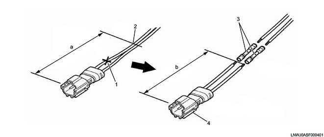
Legend
- Damaged components
- Cut location
- Joint terminal
- Connector
Dimensions
a. Length of the cut location
b. Length of the replacement connector wire
6. Wire splicing method
1. Connection method using a joint terminal (electrical wires with a diameter up to 2.0 mm2)
| Part number |
Electrical wire diameter |
Color |
Length of the electrical wire strip |
| 897169-4730 |
0.3 to 0.5 mm2 |
Yellow |
6 to 7 mm {0.24 to 0.28 in} |
| 897169-4740 |
0.75 to 1.25 mm2 |
Red |
7 to 8 mm {0.28 to 0.31 in} |
| 897169-4750 |
2.0 mm2 |
Blue |
7 to 8 mm {0.28 to 0.31 in} |
1) Strip the electrical wire repair locations and electrical extension wire.
Note
- Determine the electrical wire strip length based on the electrical wire diameter.
- Use a wire stripper of the appropriate length to avoid cutting the core wire.
2) Insert the stripped electrical wire up to the central stopper of the joint terminal.
3) Pressure bond the joint terminal using the special tool.
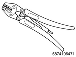
SST: 5-8741-0647-1 - terminal pincers
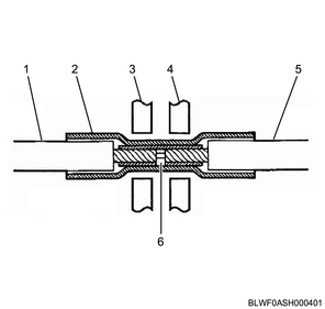
Legend
- Electrical wire
- Joint terminal
- Pressure bonding tool
- Pressure bonding tool
- Electrical extension wire
- Central stopper
Caution
- Pressure bond the joint terminal in the correct position as shown in the following diagram.
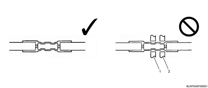
Legend
- The center of the joint terminal is pressure bonded.
- The copper sleeve end section is pressure bonded.
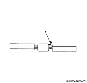
4) Heat the joint terminal surface using a heat gun, and heat shrink the outer tube.
Note
- Reference heating temperature: 120°C {248°F}
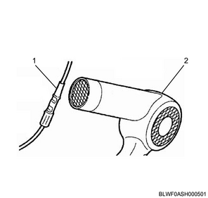
Legend
- Joint terminal
- Heat gun
Note
- Heat the tube until semitransparent resin seeps out of both ends.
- Even when the joint terminal tube is damaged and a hole forms during pressure bonding work, as long as the hole is filled with heated semitransparent resin it will be waterproof, so performing connection treatment again is unnecessary.
2. Connection treatment method using soldering (electrical wires with a diameter of 2.0 mm2 or more)
If there are no joint terminals, connect by soldering or by using commercial terminals, and perform waterproofing treatment using butyl rubber. It is recommended that joint terminals be used if connecting electrical wires with a diameter of up to 2.0 mm2.
Note
- Because of the possibility of causing open circuits, do not make connections for components with strong vibrations, such as the engine and the transmission, by soldering. Connecting by pressure bonding is recommended.
Caution
- Do not connect the following sections.
- Sections with bending and relative movement
- Sections that bear stress
- Sections that become high temperature
| Bonding type |
Part number |
Purpose |
| Pressure-bonded terminal |
Commercial product |
Bonding |
| Solder |
Commercial product |
|
| Butyl rubber |
1-82698-2630 |
Waterproofing |
| Vinyl tape |
Commercial product |
Insulation |
1) Strip the electrical wire repair locations and electrical extension wire.
Note
- For the electrical wire strip length, if there are recommended dimensions for the wiring method, then use those dimensions.
- Use a wire stripper of the appropriate length to avoid cutting the core wire.
2) Solder the overlapped section of the core wire.
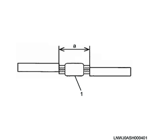
Legend
- Soldering
Dimensions
a. Core wire overlapping
3) Remove the protruding core wires and solder burrs.
Legend
- Protruding core wire, solder burrs
4) Using butyl tape, wrap the electrical wire up to the coated section to waterproof it.
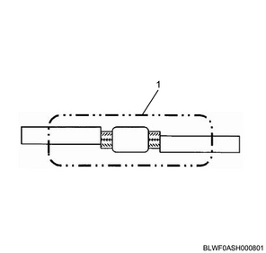
Legend
- Butyl tape
5) Using vinyl tape, completely cover the sections wrapped in butyl rubber to insulate them.
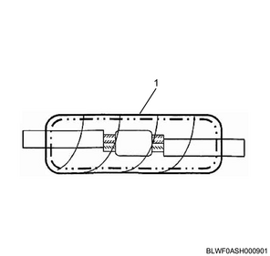
Legend
- Vinyl tape
3. Electrical wire binding method using vinyl tape
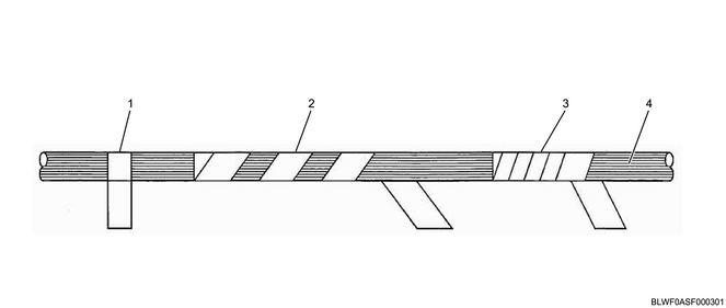
Legend
- Spot taping
- Spiral taping
- Half-overlapping
- Electrical wire
Spot taping
This is a taping method in which the same position is wrapped repeatedly, and is used for bundling electrical wires and for markings.
Spiral taping
This is a wrapping method in which each piece of tape is separated by a space equal to the width of the tape. This method is used to prevent corrugated tubes and the electrical wires inside corrugated tubes from opening.
Half-overlapping
This is a wrapping method in which each piece of tape is stacked such that it overlaps half of the previous piece. This method is used to reinforce electrical wires without protective material and corrugated tube end sections, as well as to prevent corrugated tubes from opening.

Legend
- Spot taping
- Spiral taping
- Half-overlapping
- Spot taping, spiral taping, or half-overlapping
- Electrical wire