1. Component views
Brake pedal
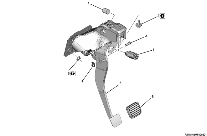
Part name
- pedal stopper
- Bolt
- Push rod pin
- Stoplight switch
- Brake pedal
- pedal pad
- Snap pin
- Nut
Tightening torque
2: 27 to 39 N・m { 2.8 to 4.0 kgf・m / 20 to 29 lb・ft }
8: 18 to 24 N・m { 1.8 to 2.4 kgf・m / 13 to 18 lb・ft }
2. Brake pedal installation
1) Install the brake pedal to the brake booster and reinforcement.
Tightening torque: 18 to 24 N・m { 1.8 to 2.4 kgf・m / 13 to 18 lb・ft } Brake booster
Tightening torque: 27 to 39 N・m { 2.8 to 4.0 kgf・m / 20 to 29 lb・ft } Reinforcement
2) Install the push rod pin from the left of the brake pedal.
3) Install the snap pin from the right of the brake pedal, and secure the push rod pin.
4) Install the pedal stopper to the brake pedal.
5) Install the pedal pad to the brake pedal.
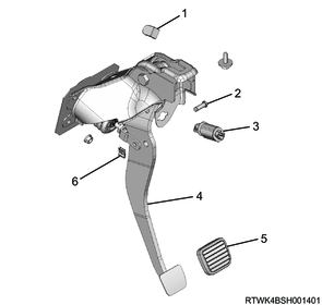
Legend
- pedal stopper
- Push rod pin
- Stoplight switch
- Brake pedal
- pedal pad
- Snap pin
3. Stoplight switch installation
1) Install the stoplight switch to the brake pedal.
4. Preliminary and post procedures
1. Post procedures
1) Connect the battery cable to the battery negative terminal.
2) Referring to the following, perform the setting of the front door power window switch with AUTO UP/AUTO DOWN function.
Refer to "9.Body, Cab, Accessories 9T.Glass, Windows, Mirrors front door power window switch setting".
3) Close the engine hood.
5. Brake pedal adjustment
When the pedal is fully depressed, the push rod operates as a pedal stopper.
1. Brake pedal measurement
1) Check whether the brake pedal completely returns.
Note
- Check based on the brake return spring state.
2) Start the engine.
3) Depress the accelerator pedal several times.
4) Measure the brake pedal height.
Note
- Adjust the brake pedal if the measured value is outside the standard range.
| Standard value |
M/T |
RHD |
175.7 to 187.7 mm { 6.92 to 7.39 in } |
| LHD |
174.6 to 186.6 mm { 6.87 to 7.35 in } |
||
| A/T |
RHD |
177.8 to 189.8 mm { 7.00 to 7.47 in } |
|
| LHD |
176.8 to 188.8 mm { 6.96 to 7.43 in } |
5) Stop the engine.
6) Depress the brake pedal 5 times or more.
7) Measure brake pedal play.
| Standard value |
6 to 10 mm { 0.24 to 0.39 in } |
|
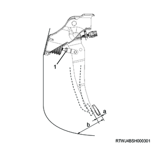
Legend
- Lock nut
Legend
a. Brake pedal free play
b. Brake pedal height
Note
- Adjust the brake pedal if the measured value is outside the standard range.
2. Brake pedal adjustment
1) Turn the stoplight switch counterclockwise to release the lock, and hold it at its fully pulled state.
2) Loosen the push rod lock nut using a wrench.
3) Turn the push rod until the brake pedal height becomes the standard value.
| Standard value |
M/T |
RHD |
175.7 to 187.7 mm { 6.92 to 7.39 in } |
| LHD |
174.6 to 186.6 mm { 6.87 to 7.35 in } |
||
| A/T |
RHD |
177.8 to 189.8 mm { 7.00 to 7.47 in } |
|
| LHD |
176.8 to 188.8 mm { 6.96 to 7.43 in } |
4) Tighten the push rod lock nut.
Tightening torque: 15 to 25 N・m { 1.5 to 2.5 kgf・m / 11 to 18 lb・ft }
Caution
- The brake pedal height should be 85 mm {3.35 in} or more when depressed with a force of approximately 490 N {50 kg/110 lb}.
3. Stoplight switch adjustment
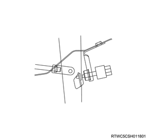
1) Verify that the stoplight switch lock is released.
Note
- If the lock is not released, release the lock by turning the stoplight switch counterclockwise.
2) Slightly pull the pedal arm forward to prevent it from being pushed in.
3) While holding the pedal arm with one hand, push the entire switch by the other hand until the pushed stoplight switch plunger causes the switch to make contact with the pedal arm rubber.
4) Turn the stoplight switch clockwise until a click is heard to lock it.
5) Check whether the clearance between the pedal arm and the stoplight switch is adjusted to 0.2 to 1.2 mm {0.008 to 0.048 in}.
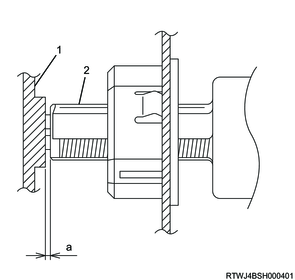
Legend
- Pedal arm
- Stoplight switch
Legend
a. Clearance