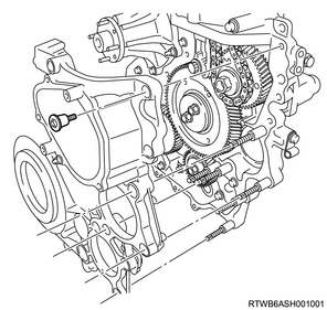
1. Component views
Timing gear case
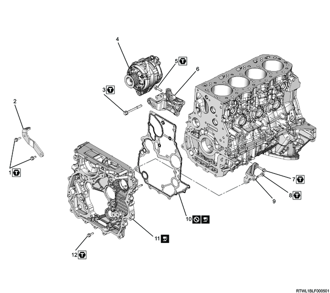
Part name
- Bolt
- Upper generator bracket
- Through bolt
- Generator
- Bolt
- Lower generator bracket
- Bolt
- Bolt
- Timing gear case bracket
- Gasket
- Timing gear case
- Bolt
Tightening torque
1: 25 N・m { 2.5 kgf・m / 18 lb・ft }
3: 40 N・m { 4.1 kgf・m / 30 lb・ft }
5: 51 N・m { 5.2 kgf・m / 38 lb・ft }
7: 25 N・m { 2.5 kgf・m / 18 lb・ft }
8: 25 N・m { 2.5 kgf・m / 18 lb・ft }
12: 25 N・m { 2.5 kgf・m / 18 lb・ft }
2. Cylinder head removal
3. Vacuum pump removal
1) Remove the vacuum pipe as a set with the vacuum hose from the timing gear case and vacuum pump.
2) Remove the vacuum pump oil pipe from the vacuum pump and cylinder block.
3) Remove the vacuum pump from the gear case cover.
4. Fuel feed pipe removal
1) Remove the fuel feed pipe from the fuel supply pump and common rail (fuel rail).
Caution
- Do not reuse the fuel feed pipe.
- Cover the exposed section to prevent the intrusion of foreign material.

Legend
- Fuel supply pump
- Fuel feed pipe
- Common rail (fuel rail)
5. Fuel leak-off pipe removal
1) Remove the fuel leak-off pipe from the fuel supply pump and common rail (fuel rail).
Caution
- Cover the exposed section to prevent the intrusion of foreign material.

Legend
- Leak-off hose
- Fuel leak-off pipe
6. Crankshaft pulley removal
1) Install the special tool to the starter installation section of the rear plate.
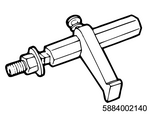
SST: 5-8840-0214-0 - crankshaft stopper
2) Remove the crankshaft pulley from the crankshaft.
Caution
- Do not reuse the crankshaft pulley bolt and washer.
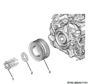
Legend
- Bolt
- Washer
- Crankshaft pulley
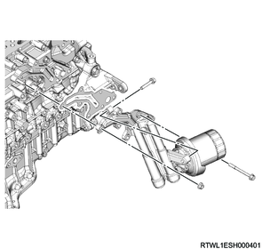
7. Oil filter removal
1) Remove the oil filter and gasket from the oil cooler.
Caution
- Do not reuse the gasket.
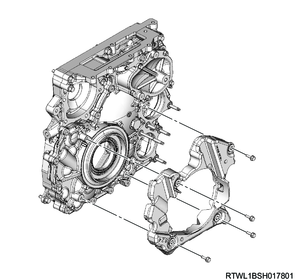
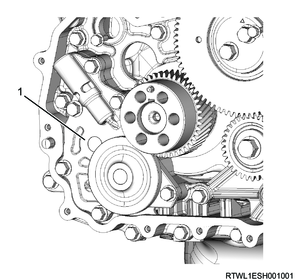
8. Tension pulley removal
1) Remove the tension pulley from the generator bracket.
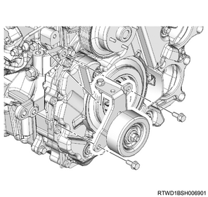
2) Remove the generator lower bracket from the cylinder block and timing gear case.
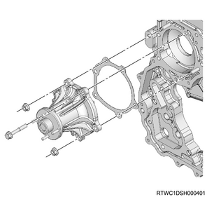
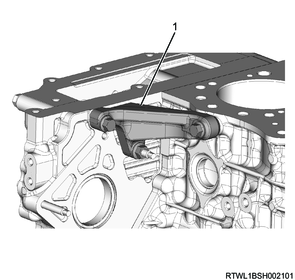
9. Water pump removal
1) Remove the water pump and gasket from the timing gear case.
Caution
- Do not reuse the gasket.
10. Power steering oil pump disconnect
1) Disconnect the power steering oil pump and power steering oil hose as a set from the timing gear case.
Legend
- Power steering oil pump
- Nut
2) Remove the power steering oil hose from the bracket.
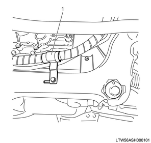
Legend
- Bracket
11. Gear case cover removal
1) Remove the cover from the gear case cover.
2) Remove the gear case cover from the timing gear case.
Caution
- Do not reuse the gasket.
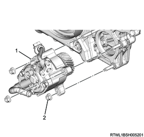
12. Oil pump removal
1) Remove the oil pump from the timing gear case.
Legend
- Oil pump
13. Supply pump gear removal
1) Apply the dial gauge to the idle gear tooth to be measured, and gently move the gear left and right to measure the fluctuation of the dial gauge.
Note
- Replace the idle gear if the measured value exceeds the standard value.
Standard: 0.10 to 0.17 mm { 0.0039 to 0.0067 in }
Limit: 0.30 mm { 0.0118 in }
2) Measure the idle gear axial direction clearance using a feeler gauge.
Note
- Replace the idle gear or thrust collar if the measured value exceeds the limit.
| Idle gear |
Standard value |
Limit |
| A |
0.055 to 0.130 mm { 0.0022 to 0.0051 in } |
0.20 mm { 0.0079 in } |
| D |
0.090 to 0.155 mm { 0.0035 to 0.0061 in } |
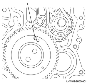
3) Turn the crankshaft in the forward direction (clockwise) to align the marks with idle gear A and the supply pump gear removal or installation position.
Note
- Referring to the diagram, align the three-dot marks.

Legend
- Supply pump installation or removal position
- TDC position
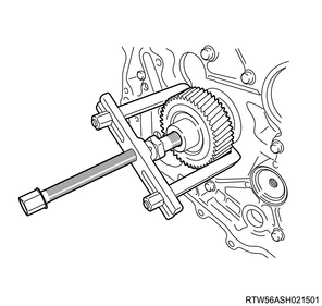
4) Install the M6 bolt for securing the sub gear to idle gear A.
Legend
- M6 bolt
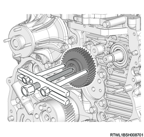
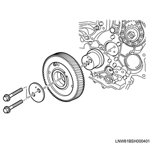
5) Remove the supply pump gear from the fuel supply pump using a gear puller.
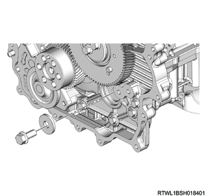
14. Idle gear removal
1) Remove the flange from idle gear A.
2) Remove idle gear A from the idle gear A shaft.
3) Remove the idle gear A shaft from the timing gear case.
4) Remove the crank gear from the crankshaft.
5) Remove idle gear D from the idle gear shaft.
6) Remove the idle gear D shaft from the camshaft brackets.
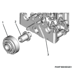
Legend
- Idle gear D
- Idle gear D shaft
- Camshaft bracket
15. Fuel supply pump removal
1) Disconnect the connector from the fuel supply pump.
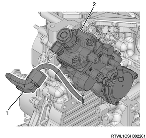
Legend
- Fuel supply pump connector
- Fuel supply pump
2) Remove the fuel supply pump from the timing gear case.
3) Remove the O-ring from the fuel supply pump.
Caution
- Do not reuse the O-ring.
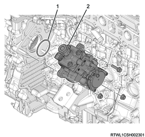
Legend
- O-ring
- Fuel supply pump
16. Timing gear case removal
1) Remove the timing gear case bracket from the timing gear case and cylinder block.
Legend
- Timing gear case bracket
2) Remove the flange bolt from the timing gear case.
3) Remove the timing gear case and gasket from the cylinder block.
Caution
- Do not reuse the gasket.
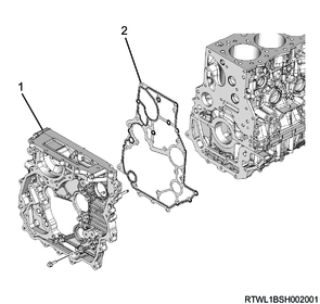
Legend
- Timing gear case
- Gasket
Caution
- Do not remove the bolts indicated by the arrows in the diagram when removing or installing the timing gear case.
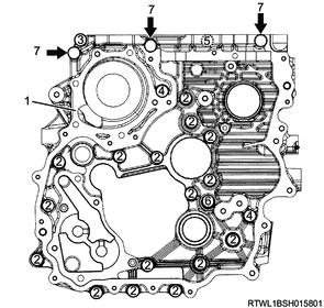
Legend
- Timing gear case
- Bolt L = 25 mm {0.98 in}
- Bolt L = 60 mm {2.36 in}
- Bolt L = 45 mm {1.77 in}
- Bolt L = 35 mm {1.38 in}
- Bolt L = 16 mm {0.63 in}
- Bolt not to be removed