1. Auto A/C control system overview
1. Auto A/C summary
The auto A/C uses various sensors to accurately detect the outside temperature, the amount of solar radiation, the temperature of the air coming out from the evaporator, and the vehicle cabin temperature. That information is input to the auto A/C control unit to automatically control the temperature of air coming from the air outlets, the air flow volume, the compressor ON and OFF, and air outlet switching. Also, manual operation of each auto-control is possible by deactivating the auto function.
The auto A/C control unit with a built-in micro-computer is equipped with a self-diagnosis function to make it easier to access and diagnose areas where there is trouble.
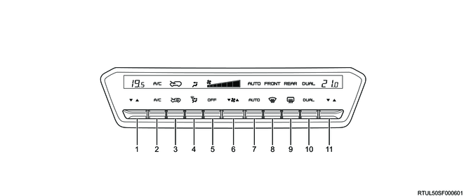
2. Control panel (Auto A/C control unit)
| No. |
Name |
Function |
| 1 |
Temperature control switch (left front seat) |
Adjusts the temperature of the passenger side. |
| 2 |
Air conditioning switch (A/C switch) |
Switches the air conditioner on and off. |
| 3 |
Inside/outside air selector switch |
Switches between inside air recirculation and outside air ventilation. |
| 4 |
Outlet selector switch |
Switches the outlets. |
| 5 |
Air conditioning off switch (OFF switch) |
Turns off the air conditioner and the fan. |
| 6 |
Fan speed control switch |
Adjusts the airflow. |
| 7 |
Automatic air conditioning switch (AUTO switch) |
Sets the air conditioner to automatic control. |
| 8 |
Windshield defroster switch |
Defogs the windshield. |
| 9 |
Rear window defogger switch |
Defogs the rear window. |
| 10 |
Dual switch |
Sets the temperature of the driver side and passenger side individually. |
| 11 |
Temperature control switch (right front seat) |
Adjusts the temperature of the driver side. |
3. Configuration chart of the auto A/C system
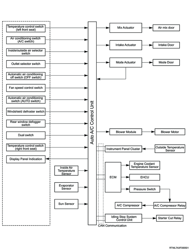
The auto A/C control unit uses calculations based on signals from various units to automatically control the fan speed and mode door opening position. These signals are input from the inside and outside air temperature sensors which detects the ambient temperature in and around the vehicle, the engine coolant temperature sensor which detect the engine coolant temperature, the evaporator sensor which detects refrigerant temperature, and the sun sensor which detects amount of solar radiation, as well as signals from control panel operation and position sensor location detection signals. The outside air temperature sensor signal and engine coolant temperature sensor signal are input to the instrument panel cluster and ECM, respectively. And then, they are sent to the auto A/C control unit via CAN communication.
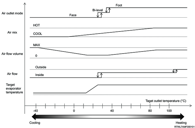
4. Auto A/C automatic control summary
The auto A/C automatically controls the following.
- Blow temperature control
- Air flow volume control
- Air outlet control
- Inlet control
- Compressor control
- Idling stop control
1) Blow temperature control
The auto A/C control unit makes calculations using the temperature setting signals and the signals from each sensor to determine the desired blow temperature. Then, it compares that with the signal from the position sensor to determine the direction of the mix actuator rotation. In response to the desired blow temperature, the mix actuator operates the air mix door to a predetermined opening position to control the blow temperature to the set temperature.
5. Air flow volume control
The auto A/C control unit makes calculations using the temperature setting signal and the signals from each sensor to determine the desired blow temperature. Then, it changes the blower module base potential to be the predetermined blower voltage in response to the desired blow temperature, and changes the blower motor speed steplessly.
When operating in manual, the fan switch has 7 levels from LO to Maximum to set the air flow volume.
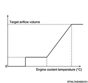
1) Warm-up control
The warm-up control prevents cold air from coming out when the heater is used with the engine coolant temperature low, such as in seasons when the outside temperature is low. The auto A/C control unit limits the air flow volume depending on the engine coolant temperature when all the following conditions are met. Also, when the blower motor is controlled to be OFF under low engine coolant temperature, the air outlet location is fixed to defroster.
- The desired blow temperature is 28°C (82°F) or more.
- The engine coolant temperature is 70°C (158°F) or less.
- The air outlet mode is "Bi-level", "Feet", or "Feet and defroster".
- The AUTO switch is ON.
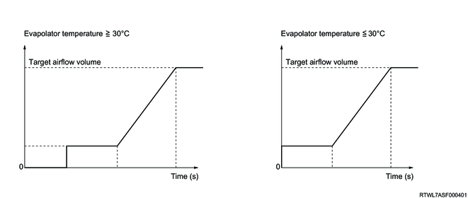
2) Cool-down control
The cool-down control prevents hot air from coming out when the A/C is used with the evaporator temperature high, such as in seasons when the outside temperature is high. The auto A/C control unit limits the air flow volume depending on the evaporator temperature when all the following conditions are met.
- The A/C switch is ON.
- The desired blow temperature is 25°C (77°F) or less.
- The air outlet mode is "Face" or "Bi-level".
- The AUTO switch is ON (*1).
Note
- *1: This condition is applied only for the first blower ON.
3) Startup control
The startup control restricts inrush current by fixing the air flow volume to LO for a predetermined period of time immediately after the blower is activated.
The auto A/C control unit fixes the air flow volume to LO for 2 seconds after the blower is turned from OFF to ON.
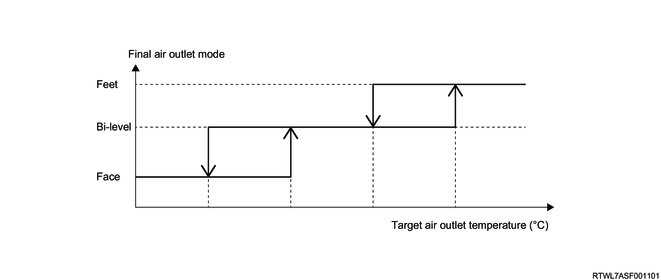
6. Air outlet control
The auto A/C control unit makes calculations using the temperature setting signals and the signals from each sensor to determine the desired blow temperature. Then, it compares that with the signal from the mode actuator position sensor to determine the operating opening position of the mode actuator. In response to the desired blow temperature, the mode actuator operates the mode door to a predetermined opening position to control the air outlet to either Face, Bi-level, or Foot.
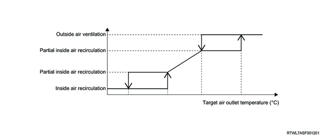
7. Inlet control
Depending on the desired blow temperature, the auto A/C control unit switches the air intake mode to either outside air intake, half-inside air recirculation, or inside air circulation.
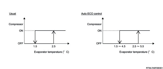
8. Compressor control
Depending on the desired blow temperature, the auto A/C control unit turns ON or OFF the compressor. The compressor ON/OFF requests are sent to the ECM via CAN communication, and the ECM performs it by controlling the compressor relay. When the evaporator temperature or outside air temperature is low, the compressor is turned OFF to prevent it from being frozen or broken.
1) Auto ECO control
The auto ECO control is a control which saves energy by decreasing the number of turning ON the compressor. When the defroster is not used during the auto ECO control, the auto A/C control unit sets the compressor-ON/OFF-determination temperature higher according to the evaporator temperature.
9. Idling stop control
The idling stop control keeps the vehicle cabin at a comfortable temperature by permitting or inhibiting idling stop depending on each temperature. When any of the following are met with the blower ON, the auto A/C control unit sends the idling stop inhibition signal to the idling stop control unit.
- Within 30 seconds after the last idling stop
- When switched to the defroster mode
- The temperature conditions where the A/C operation is necessary are met with the compressor ON.
- The temperature conditions where the heater operation is necessary are met.
- The engine automatic stop time exceeds the idling stop available time calculated based on the outside air temperature.
2. Auto A/C control components
1. Inside air temperature sensor
The inside air temperature sensor is a thermistor whose resistance changes according to temperature changes, and the resistance decreases as the temperature increases and increases as the temperature decreases. The inside air temperature sensor uses an aspirator to take in air while the blower motor is running and directs the inside air to the area around the sensor. The inside air temperature sensor is installed to the back side of the instrument panel (lower side).
RHD models
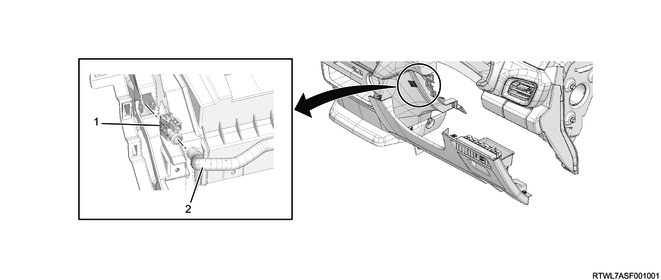
Legend
- Inside air temperature sensor
- Aspirator hose
LHD models
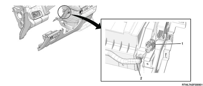
Legend
- Inside air temperature sensor
- Aspirator hose
2. Outside air temperature sensor
The outside air temperature sensor is a thermistor whose resistance changes according to temperature changes, and the resistance decreases as the temperature increases and increases as the temperature decreases. Responding to thermal effects that the condenser and radiator have on the outside air temperature sensor while idling after driving, the auto A/C control unit determines and makes necessary corrections. However, the temperature displayed rises over time. The outside air temperature sensor is installed to the lower section of the front end engine hood stay on the back of the radiator grille.
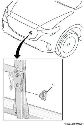
Legend
- Outside air temperature sensor
3. Evaporator temperature sensor
The evaporator temperature sensor is a thermistor whose resistance changes according to temperature changes, and the resistance decreases as the temperature increases and increases as the temperature decreases. The evaporator temperature sensor is installed to the evaporator core.
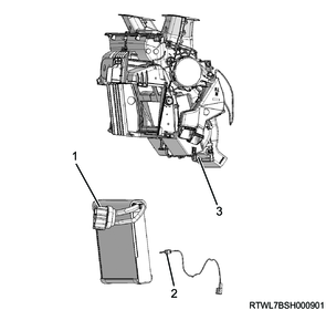
Legend
- Evaporator core
- Evaporator temperature sensor
- Heater evaporator unit
4. Sun sensor
The sun sensor is a photodiode sensor that detects the amount of solar radiation. It converts correction signals for cabin temperature changes caused by sunlight into a current and inputs this into the auto A/C control unit.
This sensor is installed at the top of the instrument panel (upper side) on the driver side.

Legend
- Sun sensor
- Instrument panel (Upper side)
5. Blower module
The blower module receives base current from the auto A/C control unit and changes the blower motor speed steplessly. The blower module is installed to the blower case.

Legend
- Blower unit
- Blower module
6. Actuator
The actuator is an electromotive device which employs a small motor to drive the heater evaporator unit and blower mode doors based on output current from the auto A/C control unit.
Among the actuators, there are a mode actuator which changes the heater evaporator unit mode, an intake actuator which changes the blower intake, and a mix actuator which changes the opening position of the air outlet.
RHD models
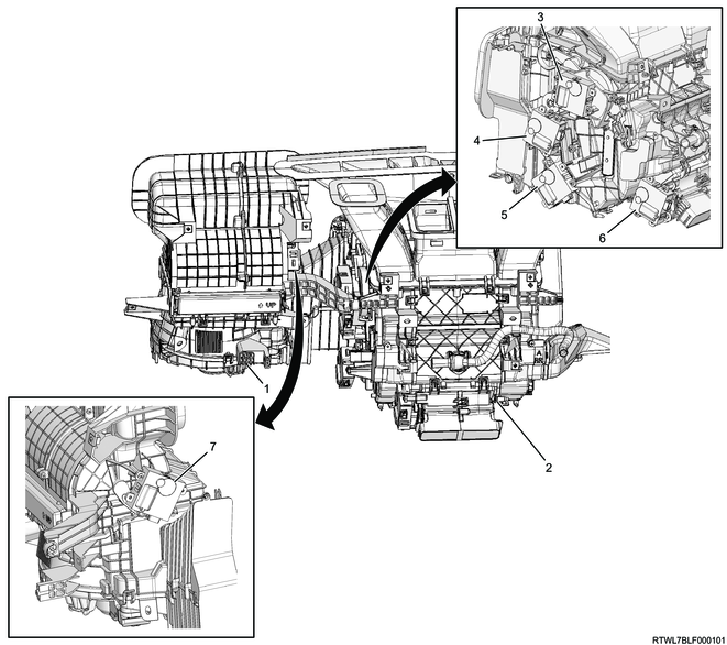
Legend
- Blower
- Heater evaporator unit
- Mode actuator
- Mix actuator (Passenger side)
- Mix actuator (Driver side)
- Rear ventilation duct actuator
- Intake actuator
LHD models

Legend
- Mode actuator
- Intake actuator
- Blower
- Rear ventilation duct actuator
- Heater evaporator unit
- Mix actuator (Driver side)
- Mix actuator (Passenger side)
7. Control panel (Auto A/C control unit)
The control section to operate the A/C and the control unit to control the A/C functions are integrated into the control panel. The control panel is installed at the center of the instrument panel.
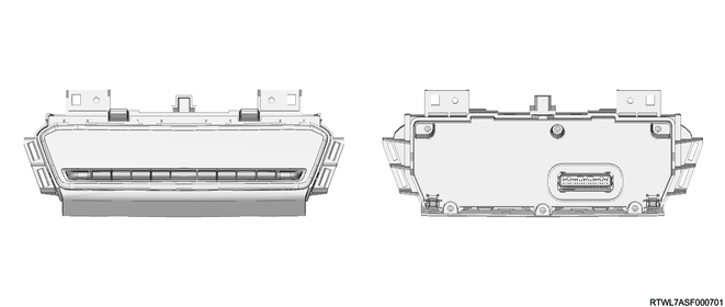
Note
- The illustration shows an RHD model.

Legend
- Control panel (Auto A/C control unit)
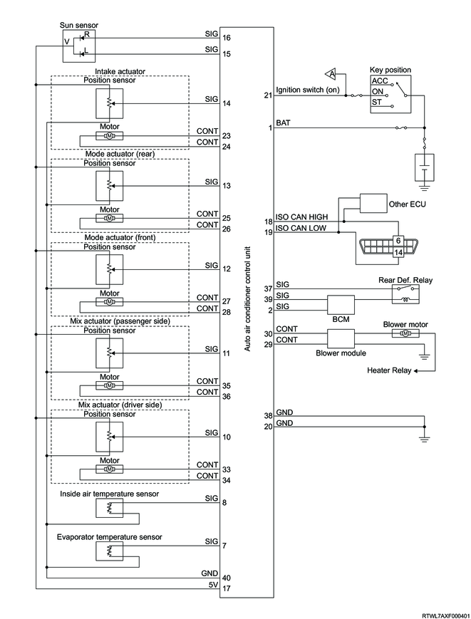
3. General circuit diagram
1. Auto A/C control unit general circuit diagram
2. Auto A/C control unit terminal layout
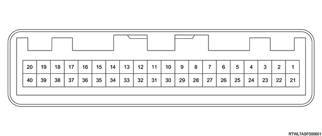
| Pin No. |
Pin Function |
| 1 |
Battery voltage |
| 2 |
Tail light switch signal (from BCM) |
| 3 |
- |
| 4 |
- |
| 5 |
- |
| 6 |
- |
| 7 |
Evaporator temperature sensor signal |
| 8 |
Inside air temperature sensor signal |
| 9 |
- |
| 10 |
Mix actuator (driver side) position sensor signal |
| 11 |
Mix actuator (passenger side) position sensor signal |
| 12 |
Mode actuator position sensor signal |
| 13 |
Rear ventilation duct actuator position sensor signal (Mode actuator (rear)) |
| 14 |
Intake actuator position sensor signal |
| 15 |
Sun sensor (passenger side) signal |
| 16 |
Sun sensor (driver side) signal |
| 17 |
Actuator position sensors and sun sensor 5 volts reference |
| 18 |
ISO CAN high |
| 19 |
ISO CAN low |
| 20 |
Ground |
| 21 |
Ignition voltage (ON) |
| 22 |
- |
| 23 |
Intake actuator drive voltage |
| 24 |
Intake actuator low side |
| 25 |
Rear ventilation duct actuator drive voltage |
| 26 |
Rear ventilation duct actuator low side |
| 27 |
Mode actuator drive voltage |
| 28 |
Mode actuator low side |
| 29 |
Blower motor drive transistor (blower module) voltage output |
| 30 |
Blower motor drive transistor (blower module) voltage input |
| 31 |
- |
| 32 |
- |
| 33 |
Mix actuator (driver side) drive voltage |
| 34 |
Mix actuator (driver side) low side |
| 35 |
Mix actuator (passenger side) drive voltage |
| 36 |
Mix actuator (passenger side) low side |
| 37 |
Rear defogger relay signal |
| 38 |
Ground |
| 39 |
Rear defogger switch signal output (to BCM) |
| 40 |
Signal ground |