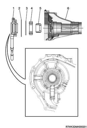
1. Component views
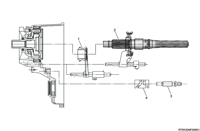
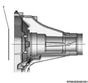
Transfer
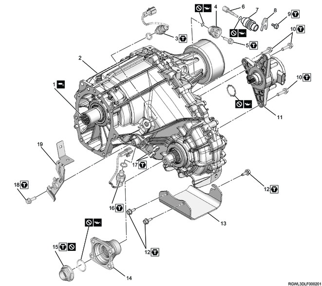
Part name
- Input shaft
- Transfer case
- 2-4 switch
- Dummy plug (Models with ABS)
- Bolt
- Speedometer driven gear (Models without ABS)
- Speedometer bushing (Models without ABS)
- Speedometer stay (Models without ABS)
- Bolt
- Bolt
- Transfer actuator
- Bolt
- Stone guard
- Front companion flange
- End nut
- Neutral switch
- Detent plug
- Bolt
- Switch bracket
Tightening torque
3: 39 N・m { 4.0 kgf・m / 29 lb・ft }
5: 15 N・m { 1.5 kgf・m / 11 lb・ft }
9: 15 N・m { 1.5 kgf・m / 11 lb・ft }
10: 22 N・m { 2.2 kgf・m / 16 lb・ft }
12: 21 N・m { 2.1 kgf・m / 15 lb・ft }
15: 137 N・m { 14.0 kgf・m / 101 lb・ft }
16: 39 N・m { 4.0 kgf・m / 29 lb・ft }
17: 19 N・m { 1.9 kgf・m / 14 lb・ft }
18: 15 N・m { 1.5 kgf・m / 11 lb・ft }
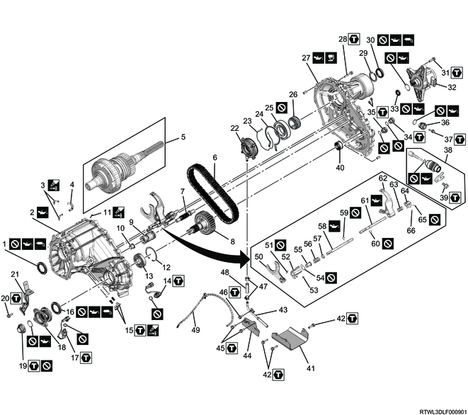
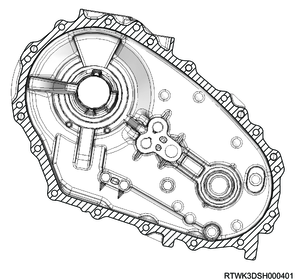
Part name
- Input shaft oil seal
- Transfer case
- Breather pipe (Transfer)
- Breather hose (Transfer)
- Main shaft assembly
- Transfer chain
- Shift drum shaft
- Front output shaft
- Shift drum
- Bushing
- Breather pipe (Actuator)
- Snap ring
- Front output shaft ball bearing
- 2-4 switch
- Detent plug, spring, and detent ball
- Front output shaft oil seal
- Neutral switch
- Front companion flange
- End nut
- Bolt
- Switch bracket
- Oil pump
- Oil pump retaining ring
- Retaining ring
- Ball bearing
- Speedometer drive gear
- Rear transfer cover
- Bolt
- Snap ring
- Rear output shaft oil seal
- Bolt
- Transfer actuator
- Shift drum oil seal
- Filler plug
- Drain plug
- Dummy plug (Models with ABS)
- Bolt
- Speedometer driven gear, speedometer bushing, and speedometer stay (Models without ABS)
- Bolt
- Needle bearing
- Stone guard
- Bolt
- Screen assembly
- Buffer plate
- Bolt
- Bolt
- Clamp
- Hose
- Breather hose (Actuator)
- H-L shift arm
- Spring pin
- H-L shift block
- Guide roller
- Inner retaining ring
- Front collar
- Shift block spring
- Rear collar
- Shift rod
- Outer snap ring
- Snap ring
- 2-4 shift rod
- 2-4 shift arm
- Shift block spring
- 2-4 shift block
- Spring pin
- Guide roller
Tightening torque
14: 39 N・m { 4.0 kgf・m / 29 lb・ft }
15: 19 N・m { 1.9 kgf・m / 14 lb・ft }
17: 39 N・m { 4.0 kgf・m / 29 lb・ft }
19: 137 N・m { 14.0 kgf・m / 101 lb・ft }
20: 15 N・m { 1.5 kgf・m / 11 lb・ft }
28: 22 N・m { 2.2 kgf・m / 16 lb・ft }
31: 22 N・m { 2.2 kgf・m / 16 lb・ft }
34: 39 N・m { 4.0 kgf・m / 29 lb・ft }
35: 39 N・m { 4.0 kgf・m / 29 lb・ft }
37: 15 N・m { 1.5 kgf・m / 11 lb・ft }
39: 15 N・m { 1.5 kgf・m / 11 lb・ft }
42: 21 N・m { 2.1 kgf・m / 15 lb・ft }
45: 15 N・m { 1.5 kgf・m / 11 lb・ft }
46: 15 N・m { 1.5 kgf・m / 11 lb・ft }
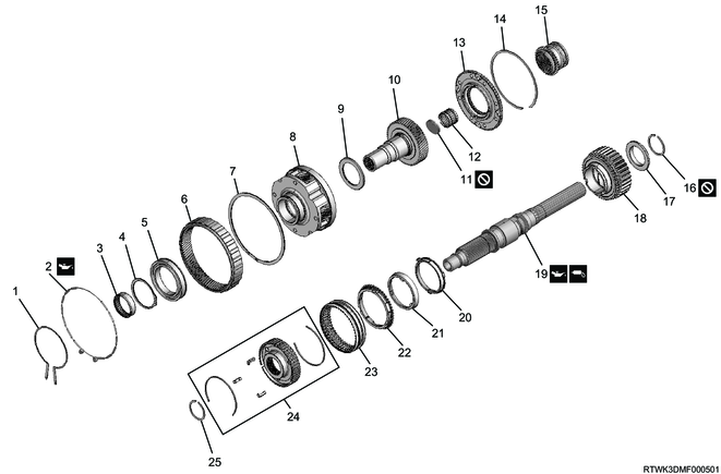
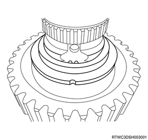
Part name
- Outer retaining ring
- Damper ring
- Needle bearing
- Carrier snap ring
- Input shaft ball bearing
- Internal gear
- Retaining ring (Spiral type)
- Carrier
- Thrust needle bearing
- Sun gear input shaft
- Seal cap
- Sun gear needle bearing
- Planetary dog teeth
- Dog teeth snap ring
- H-L sleeve
- Sprocket snap ring
- Sprocket thrust washer
- Drive sprocket
- Main shaft
- Inside ring
- Outside ring
- Block ring
- 2-4 sleeve
- Synchronizer key spring, synchronizer key, and 2-4 hub
- Hub snap ring
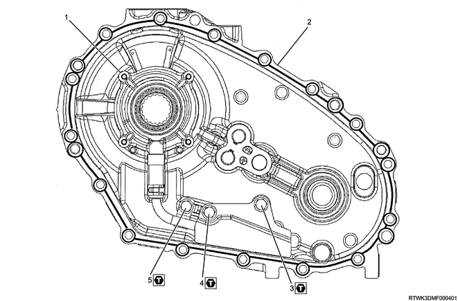
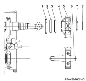
Part name
- Oil pump
- Rear transfer cover
- Bolt
- Bolt
- Bolt
Tightening torque
3: 15 N・m { 1.5 kgf・m / 11 lb・ft }
4: 15 N・m { 1.5 kgf・m / 11 lb・ft }
5: 15 N・m { 1.5 kgf・m / 11 lb・ft }
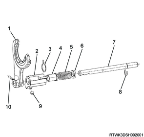
2. Shift arm installation
1. Assembly of 2-4 shift assembly
Assemble the 2-4 shift assembly according to the following procedure.
1) Install the shift block to the shift rod.
2) Install the spring pin to the shift block.
Note
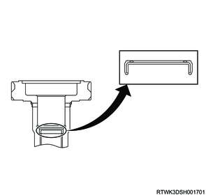
- Head of the spring pin should not stick out of the surface of shift block.
Caution
- Do not reuse the spring pin.
Legend
- Shift block surface
3) Install the spring to the shift rod.
4) Install the shift arm to the shift rod.
5) Compress the spring, and install the snap ring to the shift rod.
Caution
- Do not reuse the snap ring.
6) Install the guide roller to the shift block.

Legend
- Shift rod
- Shift arm
- Spring
- Shift block
- Spring pin
- Guide roller
- Snap ring
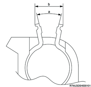
2. Assembly of H-L shift arm (Only models with pads)
1) Install the pads to the shift arm.
Note
- Apply the recommended lubricant or equivalent to the pin section of the pads.
- Press-fit the pads so that the thickness between the press-fit pin sections of the pads becomes within the standard range.
Caution
- Do not damage the pads during the press-fitting.
Standard: 7.45 to 7.98 mm { 0.293 to 0.314 in }
Note
- If the thickness between the press-fit pin sections is within the standard range, a gap between the press-fit pin section and the shift arm is allowable.
- If there is a gap near the positioning pin section due to the warpage of the pad, check that the gap near the positioning pin section is within the standard range.
Standard: 0.0 to 0.5 mm { 0.000 to 0.020 in }

Legend
- Positioning pin section
- Press-fit pin section
- Pad
- Shift arm
Standard value
a: 0.0 to 0.5 mm { 0.000 to 0.020 in } Gap
b: 7.45 to 7.98 mm { 0.293 to 0.314 in } Thickness between press-fit pin sections
Note
- After assembling the H-L shift arm, assemble it into the H-L sleeve groove and check that it slides smoothly.
3. Assembly of H-L shift assembly
Assemble the H-L shift assembly according to the following procedure.
1) Install the shift arm to the shift rod.
2) Install the spring pin to the shift arm.
Caution
- Do not reuse the spring pin.
Note
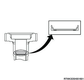
- Head of the spring pin should be at the same level as the rest of surface and should not stick out.
3) Install the front collar to the shift block.
4) Install the shift block spring to the shift block.
5) Install the rear collar to the shift block.
6) Compress the shift block spring by using the socket and vise.
7) Install the inner retaining ring to the shift block.
Note
- Clearance of the arm should be within the specified value.
Standard value
a: 25.6 °
b: 14 mm { 0.551 in }
8) Compress the H-L shift spring by using a socket and a vise.
9) Install the shift block to the shift rod.
10) Install the outer snap ring to the shift rod.
Caution
- Do not reuse the outer snap ring.
11) Install the guide roller to the shift block.
Legend
- Shift arm
- Shift block
- Inner retaining ring
- Front collar
- Shift block spring
- Rear collar
- Shift rod
- Outer snap ring
- Guide roller
- Spring pin
3. Transfer case reassembly
1) Assemble the following parts to the oil pump.
- Clamp (Screen side)
- Screen
- Clamp (Hose side)
- Hose
Note
- Tighten the clamp to secure the screen and hose.
Caution
- Pay attention to the clamp direction.
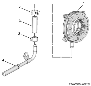
Legend
- Oil pump
- Clamp
- Hose
- Screen
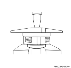
2) Install the front output shaft ball bearing to the transfer case using a press.
3) Install the snap ring to the transfer case.
Note
- Completely insert the front output shaft ball bearing, and install the snap ring to the transfer case.
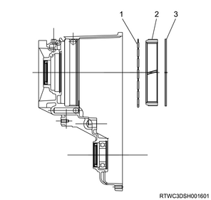
4) Apply the recommended oil or equivalent to the outer surface of the input shaft oil seal.
Caution
- Do not reuse the oil seal.
5) Clean the oil seal installation section and the surrounding area.
Caution
- Ensure that there are no burrs, etc., around the oil seal mounting section.
6) Install the input shaft oil seal to the front transfer case using the special tool.

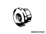
SST: 5-8840-2785-0 - oil seal installer
Caution
- When press-fitting, take care not to damage the lip section of the oil seal.
Legend
- 5-8840-2785-0
7) Apply the recommended oil or equivalent to the outer surface of the front output shaft oil seal.
Caution
- Do not reuse the oil seal.
8) Clean the oil seal installation section and the surrounding area.
Caution
- Ensure that there are no burrs, etc., around the oil seal mounting section.
9) Install the front output shaft oil seal to the front transfer case using the special tool.
SST: 5-8840-2785-0 - oil seal installer
Caution
- When press-fitting, take care not to damage the lip section of the oil seal.
Legend
- 5-8840-2785-0
10) Apply the recommended oil or grease to the damper ring.
11) Install the damper ring and internal gear to the transfer case.
Note
- Make sure that the damper ring comes between the internal gear and the transfer case.
- Installation direction of the damper ring should be as shown in the diagram.
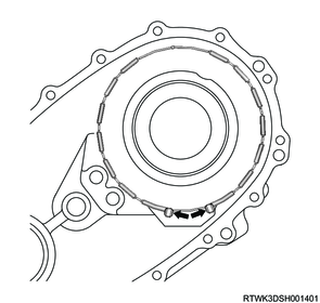
Legend
- Damper ring
- Internal gear
- Retaining ring (Spiral type)
12) Press the internal gear against the damper ring using the special tool and press.
SST: 5-8840-2784-0 - ring gear installer

Legend
- 5-8840-2784-0
13) Install the retaining ring (spiral type) to the transfer case.
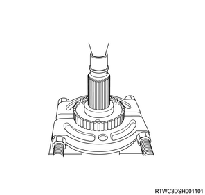
4. Input shaft installation
1) Install the needle bearing to the carrier and gear assembly using the special tool and press.
Note
- Completely insert the needle bearing into the carrier and gear assembly.

SST: 5-8840-2782-0 - bearing installer

Legend
- 5-8840-2782-0
2) Install the input shaft ball bearing to the carrier and gear assembly using the appropriate tool and press.
Note
- Completely insert the input shaft ball bearing into the carrier and gear assembly.
3) Install the carrier snap ring to the carrier.

Legend
- Carrier snap ring
4) Install the thrust needle bearing to the carrier and gear assembly.
1. AWR6B45 equipped models
1) Apply the recommended oil or equivalent to the inner surface of the sun gear input shaft.
2) Install the seal cap to the sun gear input shaft using an appropriate tool.
Caution
- Do not mistake the assembly direction of the seal cap.
- Do not reuse the seal cap.
3) Install the sun gear input shaft to the carrier and gear assembly.
4) Install the sun gear needle bearing to the carrier and gear assembly.
5) Install the planetary dog teeth to the carrier and gear assembly.
6) Install the dog teeth snap ring to the carrier and gear assembly.
7) Install the outer retaining ring to the transfer case.
8) Install the carrier and gear assembly to the transfer case using snap ring pliers.
Caution
- Fit the outer retaining ring into the groove.

Legend
- Outer retaining ring
- Carrier and gear assembly
- Thrust needle bearing
- Seal cap
- Needle bearing
- Sun gear input shaft
- Planetary dog teeth
- Dog teeth snap ring
2. MVL equipped models
1) Apply the recommended oil or equivalent to the inner surface of the sun gear input shaft.
2) Install the seal cap to the sun gear input shaft using the special tool.
Caution
- Do not mistake the assembly direction of the seal cap.
- Do not reuse the seal cap.
SST: 5-8840-3264-0 - cap seal installer

Legend
- 5-8840-3264-0
3) Install the sun gear input shaft to the carrier and gear assembly.
4) Install the sun gear needle bearing to the carrier and gear assembly.
5) Install the planetary dog teeth to the carrier and gear assembly.
6) Install the dog teeth snap ring to the carrier and gear assembly.
7) Install the outer retaining ring to the transfer case.
8) Install the carrier and gear assembly to the transfer case using snap ring pliers.
Caution
- Fit the outer retaining ring into the groove.
Legend
- Outer retaining ring
- Carrier and gear assembly
- Thrust needle bearing
- Seal cap
- Needle bearing
- Sun gear input shaft
- Planetary dog teeth
- Dog teeth snap ring
5. Transfer reassembly
1) Install the 2-4 hub to the main shaft using a press.
2) Install the hub snap ring to the main shaft.
3) Install the following parts to the 2-4 hub.
- Synchronizer key spring
- Synchronizer key
- 2-4 sleeve
Note
- Face the opening sections of the synchronizer key and key spring end opposite each other.
4) Install the H-L sleeve to the main shaft.

Legend
- H-L sleeve
- 2-4 sleeve
- Synchronizer key and key spring
- Hub snap ring
5) Install the bushing to the transfer case.
Note
- Press-fit until it makes contact with the flange of the bushing.
6) Apply the recommended oil to the periphery of each shift assembly insertion hole of the transfer case.
7) Install the main shaft, H-L shift assembly, and 2-4 shift assembly as a set to the shift drum.
8) Align the shift drum shaft spline with the shift drum.
9) Install the shift drum shaft to the shift drum.
10) Referring to the diagram, install the following parts to each shift assembly insertion hole.
- H-L sleeve and H-L shift assembly
- Main shaft and shift arm with 2-4 sleeve assembly
- Shift drum shaft
Legend
- H-L sleeve and H-L shift assembly
- Main shaft and shift arm with 2-4 sleeve assembly
- Shift drum shaft
- Shift drum
Caution
- Pay attention to the direction of the assembly.

11) Apply the recommended oil or equivalent to the main shaft.
12) Install the following parts to the main shaft.
- Block ring
- Outside ring
- Inside ring
Note
- Align the block ring, outside ring, and inside ring with the 2-4 hub assembly, and install them.
13) Install the drive sprocket, transfer chain, and front output shaft to the main shaft and transfer case.
14) Align the sprocket thrust washer with the main shaft groove in a straight line.
15) Install the sprocket thrust washer to the main shaft.
16) Select the main shaft sprocket snap ring.
Note
- Select the sprocket snap ring that minimizes the shaft play.
- Install the sprocket snap ring to the main shaft mounting groove.
Caution
- Do not reuse the sprocket snap ring.
| Snap ring thickness |
Identification color |
| 2.15 mm { 0.085 in } |
Red |
| 2.10 mm { 0.083 in } |
No identification color |
| 2.05 mm { 0.081 in } |
Blue |
| 2.00 mm { 0.079 in } |
White |
Legend
- Block ring
- Outside ring
- Inside ring
- Sprocket
- Chain
- Front output shaft
- Thrust washer
- Sprocket snap ring
17) Measure the snap ring outer diameter using a vernier caliper, and use a sprocket snap ring whose standard value is the measured value.
Standard: 53 to 54 mm { 2.09 to 2.13 in }
18) Install the shift rod hole plug to the rear transfer cover.
Note
- Replace with new parts as necessary.
Caution
- Press-fit until it is flush with the rear cover surface.
19) Place the rear cover so that the mating surface is facing up.
20) Install the front output shaft needle bearing to the rear transfer cover using the special tool and press.
SST: 5-8840-2783-0 - bearing installer
Note
- Align the surface marked with the name of the bearing manufacturer with the special tool.

Legend
- 5-8840-2783-0
21) Install the oil pump wire snap ring to the rear cover.
Legend
- Wire snap ring
22) Temporarily install the speedometer drive gear to the rear cover.
Note
- Temporarily install to the inside of the rear cover.
Caution
- Pay careful attention to the installation direction so that the side of the speedometer drive gear with the groove is on the oil pump side.
23) Install the rear output shaft ball bearing to the rear transfer cover using the special tool and press.
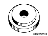
SST: 9-8522-1274-0 - bearing installer
Caution
- Do not reuse the rear output shaft ball bearing.
- Do not tap to insert the ball bearing with a hammer.
Legend
- 9-8522-1274-0
24) Install the rear output shaft retaining ring to the rear transfer cover.
25) Place the oil pump to the rear transfer cover installation position.
26) Install the oil pump strainer to the rear cover.
Tightening torque: 15 N・m { 1.5 kgf・m / 11 lb・ft }
Legend
- Oil pump
- Wire snap ring
- Retaining ring
- Ball bearing
- Speedometer drive gear
- Rear cover
27) Apply LOCTITE FMD127 or equivalent to the rear transfer cover, within the shaded range as shown in the diagram.
Caution
- The state of liquid gasket application should have no breaks or misalignment.
- Confirm that there is no dirt or oil attached to the application surface of the liquid gasket.
28) Install the rear cover to the transfer case.
Tightening torque: 22 N・m { 2.2 kgf・m / 16 lb・ft }
29) Apply the recommended oil or equivalent to the companion flange O-ring.
Caution
- Do not reuse the companion flange O-ring.
30) Install the companion flange O-ring to the output shaft.
31) Install the front companion flange to the output shaft.
32) Install the end nut to the output shaft using the special tool.
SST: 5-8840-0133-0(J-8614-11) - flange holder
Note
- Secure the front companion flange using the special tool.
Caution
- Do not reuse the front companion flange end nut.
Tightening torque: 137 N・m { 14.0 kgf・m / 101 lb・ft }
Legend
- 5-8840-0133-0 (J-8614-11)
33) Crimp the front companion flange end nut using the special tool.

SST: 5-8840-2293-0 - end nut lock punch
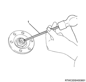
Legend
- 5-8840-2293-0
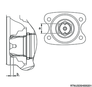
Dimensions
a: 26 mm { 1.02 in } Maximum value
b: 4 mm { 0.16 in } Minimum value
34) Install the main shaft snap ring to the rear output shaft using the special tool.
Note
- Install it from behind the shaft to make sure that it fits to the groove securely.
Caution
- Do not reuse the main shaft snap ring.
SST: 5-8840-2787-0 - snap ring installer

Legend
- 5-8840-2787-0
35) Clean the oil seal installation section and the surrounding area.
Caution
- Ensure that there are no burrs, etc., around the oil seal mounting section.
36) Apply the recommended oil or equivalent to the outer surface of the rear output shaft oil seal.
Caution
- Do not reuse the oil seal.
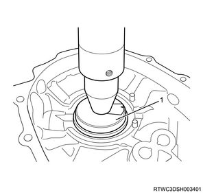
37) Install the rear output shaft oil seal to the transfer case using the special tool.
SST: 5-8840-3162-0 - oil seal installer
Caution
- When press-fitting, take care not to damage the lip section of the oil seal.

Legend
- 5-8840-3162-0
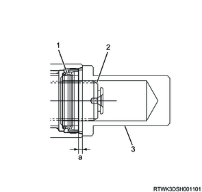
Legend
- Rear output shaft oil seal
- Main shaft
- 5-8840-3162-0
Standard value
a: 3.5 to 4.5 mm { 0.138 to 0.177 in }
38) Apply LOCTITE 575 or equivalent to the threaded portion of the detent plug.
39) Install the following parts to the transfer case.
- Detent ball (2 pcs.)
- Detent spring (2 pcs.)
- Detent plug (2 pcs.)
Tightening torque: 19 N・m { 1.9 kgf・m / 14 lb・ft }
40) Install the neutral switch of the brown harness cover to the transfer case.
Tightening torque: 39 N・m { 4.0 kgf・m / 29 lb・ft }
41) Install the 2-4 switch of the gray harness cover to the transfer case.
Tightening torque: 39 N・m { 4.0 kgf・m / 29 lb・ft }
42) Install the switch bracket to the transfer case.
Tightening torque: 15 N・m { 1.5 kgf・m / 11 lb・ft }
43) Apply the recommended oil or equivalent to the shift drum oil seal.
44) Install the shift drum oil seal to the rear transfer cover.
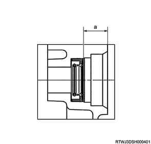
Standard value
a: 17.4 to 17.9 mm { 0.685 to 0.705 in } Press-fitting depth
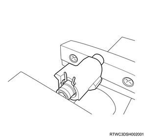
45) Install the transfer actuator to the transfer case.
Note
- Install the transfer actuator in the same direction as the shaft.
Tightening torque: 22 N・m { 2.2 kgf・m / 16 lb・ft }
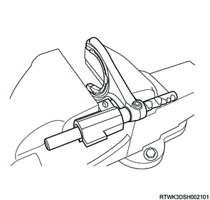
46) Apply LOCTITE 326 or equivalent to the breather pipe (transfer) and breather pipe (actuator).
47) Referring to the diagram, install the breather pipe (transfer) and breather pipe (actuator) to the transfer case.
48) Install the transfer hose between the breather pipe (transfer) and the breather pipe (actuator).

Standard value
a: 65 °
b: 14 to 16 mm { 0.55 to 0.63 in }
49) Install the breather hose between the breather pipe (actuator) and the transfer actuator.
6. Speedometer driven gear installation
1. Models with ABS
1) Install the O-ring to the dummy plug.
Note
- Apply the recommended oil or equivalent to the O-ring.
Caution
- Do not reuse the O-ring.
2) Install the dummy plug to the rear transfer cover.
Tightening torque: 15 N・m { 1.5 kgf・m / 11 lb・ft }
2. Models without ABS
1) Install the O-ring to the speedometer bushing.
Note
- Apply the recommended oil or equivalent to the O-ring.
Caution
- Do not reuse the O-ring.
2) Install the following parts to the rear transfer cover.
- Speedometer driven gear
- Speedometer bushing
- Speedometer stay
Tightening torque: 15 N・m { 1.5 kgf・m / 11 lb・ft }
7. Stone guard installation
1) Install the stone guard to the transfer case.
Tightening torque: 21 N・m { 2 kgf・m / 15 lb・ft }