1. Component views
Clutch control (RZ4E)
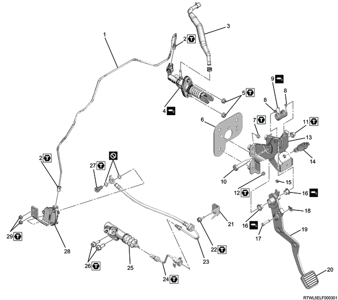
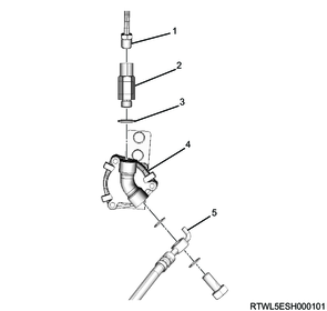
Part name
- Oil pipe
- Connector
- Oil hose
- Clutch master cylinder
- Nut
- Plate
- Plate bolt
- Assist spring bushing
- Assist spring
- Fulcrum pin
- Fulcrum pin nut
- Clutch pedal nut
- Clutch pedal bracket
- Clutch switch
- Assist spring bushing
- Fulcrum pin busing
- Clevis pin
- Pin
- Clutch pedal
- Clutch pedal rubber
- Oil hose bracket
- Bolt
- Oil hose
- Oil pipe
- Slave cylinder
- Bolt
- Eyebolt
- Damper cylinder
- Nut
Tightening torque
2: 20 N・m { 2.0 kgf・m / 15 lb・ft }
5: 23 N・m { 2.3 kgf・m / 17 lb・ft }
7: 9.4 N・m { 1.0 kgf・m / 83 lb・in }
11: 32 N・m { 3.3 kgf・m / 24 lb・ft }
12: 21 N・m { 2.1 kgf・m / 15 lb・ft }
22: 25 N・m { 2.5 kgf・m / 18 lb・ft }
24: 20 N・m { 2.0 kgf・m / 15 lb・ft }
26: 43 N・m { 4.4 kgf・m / 32 lb・ft }
27: 34 N・m { 3.5 kgf・m / 25 lb・ft }
29: 8 N・m { 0.8 kgf・m / 71 lb・in }
Clutch control (4JJ3 except dual mass flywheel specifications)
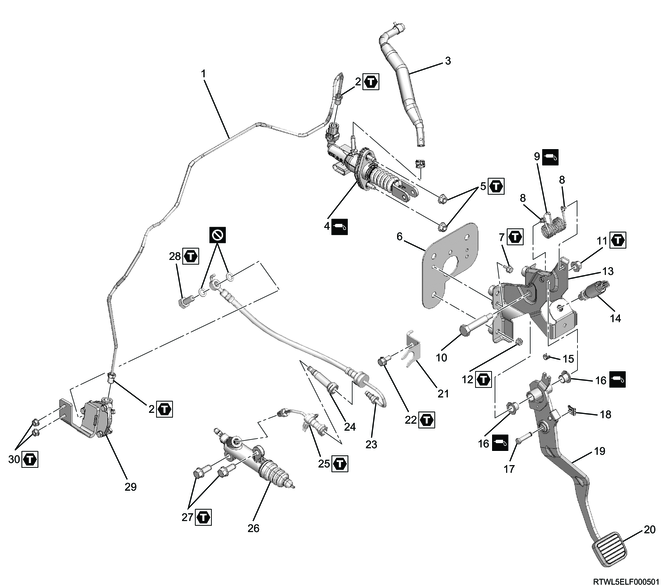
Part name
- Oil pipe
- Connector
- Oil hose
- Clutch master cylinder
- Nut
- Plate
- Plate bolt
- Assist spring bushing
- Assist spring
- Fulcrum pin
- Fulcrum pin nut
- Clutch pedal nut
- Clutch pedal bracket
- Clutch switch
- Assist spring bushing
- Fulcrum pin busing
- Clevis pin
- Pin
- Clutch pedal
- Clutch pedal rubber
- Oil hose bracket
- Bolt
- Oil hose
- Orifice
- Oil pipe
- Slave cylinder
- Bolt
- Eyebolt
- Damper cylinder
- Nut
Tightening torque
2: 20 N・m { 2.0 kgf・m / 15 lb・ft }
5: 23 N・m { 2.3 kgf・m / 17 lb・ft }
7: 9.4 N・m { 1.0 kgf・m / 83 lb・in }
11: 32 N・m { 3.3 kgf・m / 24 lb・ft }
12: 21 N・m { 2.1 kgf・m / 15 lb・ft }
22: 25 N・m { 2.5 kgf・m / 18 lb・ft }
25: 20 N・m { 2.0 kgf・m / 15 lb・ft }
27: 43 N・m { 4.4 kgf・m / 32 lb・ft }
28: 34 N・m { 3.5 kgf・m / 25 lb・ft }
30: 8 N・m { 0.8 kgf・m / 71 lb・in }
Clutch control (4JJ3 dual mass flywheel specifications)
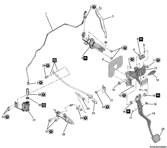
Part name
- Oil pipe
- Connector
- Oil hose
- Clutch master cylinder
- Nut
- Plate
- Plate bolt
- Assist spring bushing
- Assist spring
- Fulcrum pin
- Fulcrum pin nut
- Clutch pedal nut
- Clutch pedal bracket
- Clutch switch
- Assist spring bushing
- Fulcrum pin busing
- Clevis pin
- Pin
- Clutch pedal
- Clutch pedal rubber
- Oil hose bracket
- Bolt
- Oil hose
- Orifice
- Oil pipe
- Slave cylinder
- Bolt
- Eyebolt
- Damper
- Gasket
- Damper cylinder
- Nut
Tightening torque
2: 20 N・m { 2.0 kgf・m / 15 lb・ft }
5: 23 N・m { 2.3 kgf・m / 17 lb・ft }
7: 9.4 N・m { 1.0 kgf・m / 83 lb・in }
11: 32 N・m { 3.3 kgf・m / 24 lb・ft }
12: 21 N・m { 2.1 kgf・m / 15 lb・ft }
22: 25 N・m { 2.5 kgf・m / 18 lb・ft }
25: 20 N・m { 2.0 kgf・m / 15 lb・ft }
27: 43 N・m { 4.4 kgf・m / 32 lb・ft }
28: 34 N・m { 3.5 kgf・m / 25 lb・ft }
29: 20 N・m { 2.0 kgf・m / 15 lb・ft }
32: 8 N・m { 0.8 kgf・m / 71 lb・in }
2. Slave cylinder installation
1. RZ4E
1) Install the damper cylinder to the tire house panel.
Tightening torque: 8 N・m { 0.8 kgf・m / 71 lb・in }
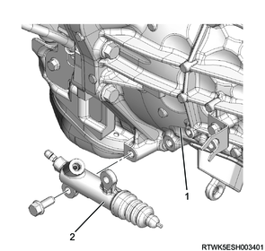
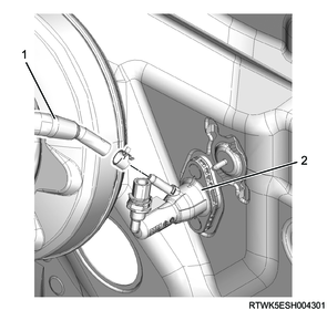
2) Temporarily tighten the slave cylinder to the transmission.
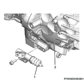
Legend
- Slave cylinder
- Transmission
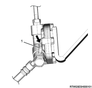
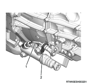
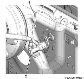
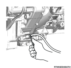
3) Temporarily tighten the oil pipe to the slave cylinder.
Legend
- Slave cylinder
- Oil pipe
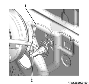
4) Install the band clip to the transmission.

Legend
- Oil pipe
- Band clip
5) Final tighten the slave cylinder to the transmission.
Tightening torque: 43 N・m { 4.4 kgf・m / 32 lb・ft }
6) Final tighten the oil pipe to the slave cylinder.
Tightening torque: 20 N・m { 2.0 kgf・m / 15 lb・ft }
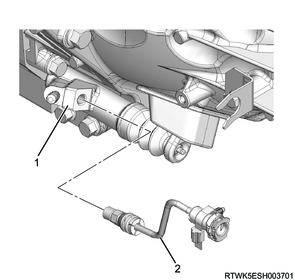
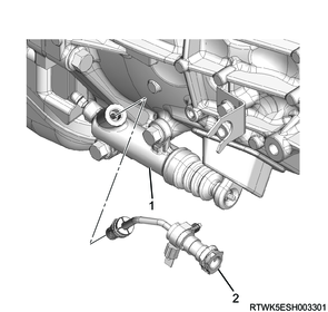
7) Install the oil hose to the oil pipe connector.
Note
- Securely insert until full contact is made.

Legend
- Oil pipe connector
- Oil hose
8) Apply soapy water to the bushing.
9) Install the bushing to the oil hose bracket.

Legend
- Oil hose bracket
- Bushing
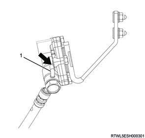
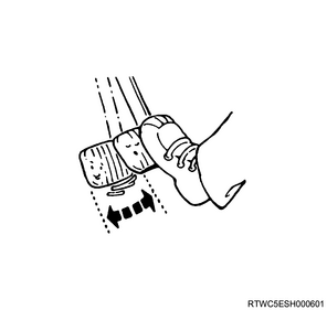
10) Install the oil hose and gasket to the damper cylinder.
Note
- Tighten the flexible hose pin while it makes contact with the damper cylinder.
Caution
- Do not reuse the gasket.
Tightening torque: 34 N・m { 3.5 kgf・m / 25 lb・ft }
Legend
- Pin
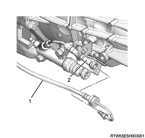
11) Install the oil pipe to the damper cylinder.
Tightening torque: 20 N・m { 2.0 kgf・m / 15 lb・ft }
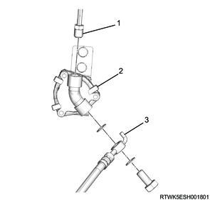
Legend
- Oil pipe
- Damper cylinder
- Oil hose
2. 4JJ3 (Except dual mass flywheel specifications)
1) Install the damper cylinder to the tire house panel.
Tightening torque: 8 N・m { 0.8 kgf・m / 71 lb・in }
2) Temporarily tighten the slave cylinder to the transmission.
Legend
- Transmission
- Slave cylinder
3) Temporarily tighten the oil pipe to the slave cylinder.
Legend
- Slave cylinder
- Oil pipe
4) Install the band clip to the transmission.
Legend
- Oil pipe
- Band clip
5) Final tighten the slave cylinder to the transmission.
Tightening torque: 43 N・m { 4.4 kgf・m / 32 lb・ft }
6) Final tighten the oil pipe to the slave cylinder.
Tightening torque: 20 N・m { 2.0 kgf・m / 15 lb・ft }
7) Install the orifice to the oil pipe connector.

Legend
- Oil pipe connector
- Orifice
8) Install the oil hose to the orifice.
Note
- Securely insert until full contact is made.
Legend
- Oil hose
- Orifice
9) Apply soapy water to the bushing.
10) Install the bushing to the oil hose bracket.

Legend
- Oil hose bracket
- Bushing
11) Install the oil hose and gasket to the damper cylinder.
Note
- Tighten the flexible hose pin while it makes contact with the damper cylinder.
Caution
- Do not reuse the gasket.
Tightening torque: 34 N・m { 3.5 kgf・m / 25 lb・ft }
Legend
- Pin
12) Install the oil pipe to the damper cylinder.
Tightening torque: 20 N・m { 2.0 kgf・m / 15 lb・ft }
Legend
- Oil pipe
- Damper cylinder
- Oil hose
3. 4JJ3 (Dual mass flywheel specifications)
1) Install the damper cylinder to the tire house panel.
Tightening torque: 8 N・m { 0.8 kgf・m / 71 lb・in }
2) Temporarily tighten the slave cylinder to the transmission.
Legend
- Transmission
- Slave cylinder
3) Temporarily tighten the oil pipe to the slave cylinder.
Legend
- Slave cylinder
- Oil pipe
4) Install the band clip to the transmission.
Legend
- Oil pipe
- Band clip
5) Final tighten the slave cylinder to the transmission.
Tightening torque: 43 N・m { 4.4 kgf・m / 32 lb・ft }
6) Final tighten the oil pipe to the slave cylinder.
Tightening torque: 20 N・m { 2.0 kgf・m / 15 lb・ft }
7) Install the orifice to the oil pipe connector.
Legend
- Oil pipe connector
- Orifice
8) Install the oil hose to the orifice.
Note
- Securely insert until full contact is made.
Legend
- Oil hose
- Orifice
9) Apply soapy water to the bushing.
10) Install the bushing to the oil hose bracket.
Legend
- Oil hose bracket
- Bushing
11) Install the oil hose and gasket to the damper cylinder.
Note
- Tighten the flexible hose pin while it makes contact with the damper cylinder.
Caution
- Do not reuse the gasket.
Tightening torque: 34 N・m { 3.5 kgf・m / 25 lb・ft }
Legend
- Pin
12) Temporarily tighten the damper to the damper cylinder.
13) Final tighten the damper to the damper cylinder.
Tightening torque: 20 N・m { 2.0 kgf・m / 15 lb・ft }
14) Temporarily tighten the oil pipe to the damper.
15) Final tighten the oil pipe to the damper.
Tightening torque: 20 N・m { 2.0 kgf・m / 15 lb・ft }
Legend
- Oil pipe
- Damper
- Gasket
- Damper cylinder
- Oil hose
3. Clutch master cylinder installation
1. RZ4E
1) Install the clutch master cylinder to the dash panel.
Tightening torque: 23 N・m { 2.3 kgf・m / 17 lb・ft }

2) Install the oil hose to the clutch master cylinder.
Legend
- Oil hose
- Clutch master cylinder
3) Connect the oil pipe to the clutch master cylinder.
Tightening torque: 20 N・m { 2.0 kgf・m / 15 lb・ft }
Legend
- Oil pipe
- Clutch master cylinder
2. 4JJ3
1) Install the clutch master cylinder to the dash panel.
Tightening torque: 23 N・m { 2.3 kgf・m / 17 lb・ft }
2) Install the oil hose to the clutch master cylinder.

Legend
- Oil hose
- Clutch master cylinder
3) Connect the oil pipe to the clutch master cylinder.
Tightening torque: 20 N・m { 2.0 kgf・m / 15 lb・ft }
Legend
- Oil pipe
- Clutch master cylinder
4) Connect the connector to the clutch master cylinder.
4. Clutch pedal installation
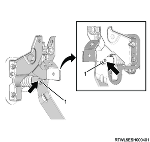
1) Apply BESCO chassis grease or equivalent to the assist spring between coils and rotation sliding section.
2) Install the plate bolt to the clutch pedal.
Tightening torque: 9.4 N・m { 1.0 kgf・m / 83 lb・in }
3) Install the clutch pedal nut to the dash panel.
Tightening torque: 21 N・m { 2.1 kgf・m / 15 lb・ft }
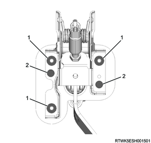
Legend
- Clutch pedal nut
- Plate bolt
4) Apply BESCO rubber grease or equivalent to the rotation sliding section of the clevis pin.
Standard: 1 g { 0.04 oz } Application amount
Legend
- Clevis (Master cylinder)
5) Install the clevis pin to the clutch pedal.
6) Install the pin to the clevis pin.
Legend
- Clevis pin
- Pin
7) Connect the harness connector to the clutch switch.
5. Clutch pedal inspection
1) Lightly press the clutch pedal with a hand to inspect that the play is within the standard value range.
Standard: 5.0 to 15.0 mm { 0.2 to 0.6 in }
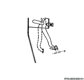
Standard value
a: 5.0 to 15.0 mm { 0.2 to 0.6 in } Play
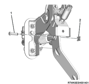
6. Clutch switch adjustment
1) Loosen the lock nut using a wrench.
2) Turn the clutch switch to adjust the clearance so that it is within the standard range.
Standard: 0.5 to 1.5 mm { 0.020 to 0.059 in } Clearance
3) After adjustment, tighten the lock nut.
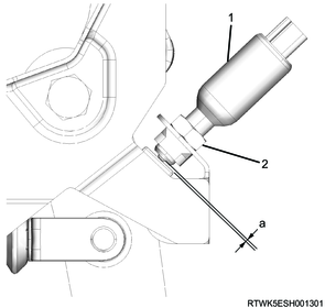
Legend
- Clutch switch
- Lock nut
Standard value
a: 0.5 to 1.5 mm { 0.020 to 0.059 in } Clearance
7. Clutch fluid air bleed
1) Apply the parking brake.
Note
- Fully pull the parking brake lever.
2) Clean passages of clutch master cylinder, slave cylinder, piping, etc., using an air blower.
3) Add brake fluid up to the reservoir tank MAX level and wait 1 minute or more.
Note
- The clutch fluid reservoir tank is shared with the brake fluid reservoir tank.
- The fluid levels in the clutch fluid chamber and brake fluid chamber differ because of partitioning inside the reserve tank, and so the clutch fluid level needs to be checked on the clutch chamber side.
Caution
- Because brake fluid will decrease during the air bleeding process, take care to prevent the reservoir tank from becoming empty.
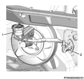
Legend
- Reservoir tank
- Clutch master cylinder
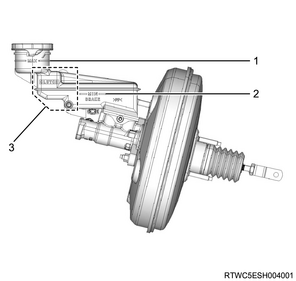
Legend
- MAX level
- MIN level
- Clutch fluid compartment
4) Connect the vinyl tube to the bleeder screw, and insert the other end into a container filled with brake fluid.
5) Depress the clutch pedal 3 times and hold it down.
Note
- Depress the clutch pedal at the rate of 60 mm/sec, and return the pedal at the rate of 40 mm/sec.
6) Loosen the bleeder screw 1/3 of a turn using a wrench to discharge the brake fluid.
7) Tighten the bleeder screw using a wrench.
Note
- Release the clutch pedal after tightening the bleeder screw.
8) Repeat the process from depressing the clutch pedal to opening/closing the bleeder screw at intervals of 2 seconds.
Caution
- Repeat the operation 30 times or more until all air is completely discharged.
RZ4E
4JJ3

8. Preliminary and post procedures
1. Post procedures
1) Lower the vehicle.
2) Connect the battery cable to the battery negative terminal.
3) Referring to the following, perform the setting of the front door power window switch with AUTO UP/AUTO DOWN function.
Refer to "9.Body, Cab, Accessories 9T.Glass, Windows, Mirrors front door power window switch setting".