1. Inhibitor switch installation
1) Install the inhibitor switch onto the manual valve lever shaft and temporarily install the bolt.
Note
- Tighten the bolt after adjusting the inhibitor switch to the N position.
2) Install the new lock washer with the new nut to the inhibitor switch.
Caution
- Do not reuse the lock washers and nuts.
Tightening torque: 7 N・m { 0.7 kgf・m / 62 lb・in }
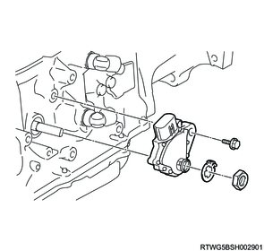
3) Using a screwdriver, stake the lock washer.

2. Engine harness connect
1) Connect the engine harness to the inhibitor switch.
3. Preliminary and post procedures
1. Post procedures
1) Lower the vehicle.
2) Connect the battery cable to the battery negative terminal.
3) Referring to the following, perform the setting of the front door power window switch with AUTO UP/AUTO DOWN function.
Refer to "9.Body, Cab, Accessories 9T.Glass, Windows, Mirrors front door power window switch setting".
4) Close the engine hood.
4. Inhibitor switch adjustment
1) Inspect that the engine can be started with the shift lever at N or P only, but not in other range.
2) Set the select lever assembly in N range and remove the automatic transmission control cable.
3) Make sure the neutral basic line align with the groove.
Note
- If a problem is found, adjust the inhibitor switch.
4) Loosen the inhibitor switch bolt.
5) Adjust the manual valve lever shaft to the N position.
6) Align the groove and neutral basic line.
7) Hold in position and tighten the bolt.
Tightening torque: 13 N・m { 1.3 kgf・m / 115 lb・in }
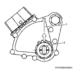
Legend
- Neutral basic line
- Groove