1. Component views
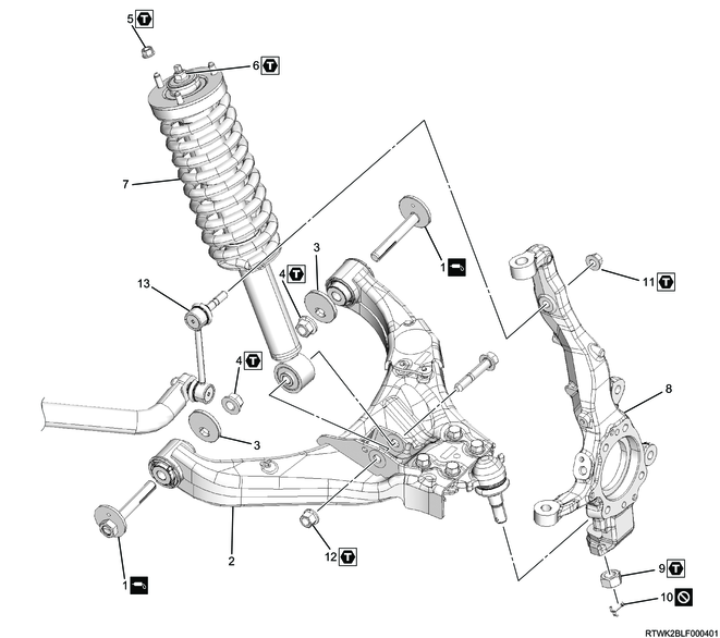
Coil spring
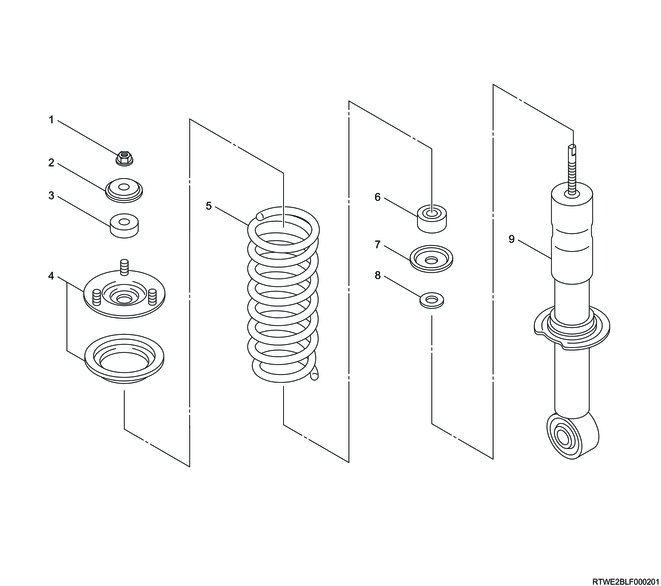
Part name
- Nut
- Washer
- Rubber bushing
- Front mount bracket
- Coil spring
- Rubber bushing
- Washer
- Washer
- Shock absorber
Shock absorber (2WD (Except high ride suspension specification))
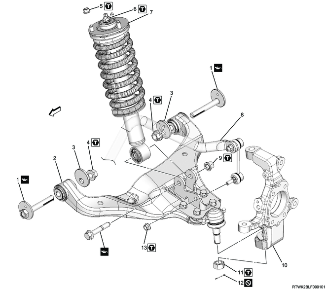
Part name
- Cam bolt
- Lower link
- Cam plate
- Nut
- Nut
- Nut
- Shock absorber assembly
- Stabilizer bar
- Nut
- Knuckle
- Nut
- Cotter pin
- Nut
Tightening torque
4: 186 N・m { 19.0 kgf・m / 137 lb・ft }
5: 55 N・m { 5.6 kgf・m / 41 lb・ft }
6: 25 N・m { 2.5 kgf・m / 18 lb・ft }
9: 152 N・m { 15.5 kgf・m / 112 lb・ft }
11: 147 N・m { 15.0 kgf・m / 108 lb・ft }
13: 64 N・m { 6.5 kgf・m / 47 lb・ft }
Stabilizer bar (2WD (Except high ride suspension specification))
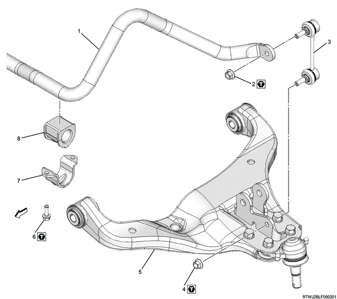
Part name
- Stabilizer bar
- Nut
- Stabilizer link
- Nut
- Lower link
- Bolt
- Clamp
- Rubber bushing
Tightening torque
2: 64 N・m { 6.5 kgf・m / 47 lb・ft }
4: 64 N・m { 6.5 kgf・m / 47 lb・ft }
6: 47.1 N・m { 4.8 kgf・m / 35 lb・ft }
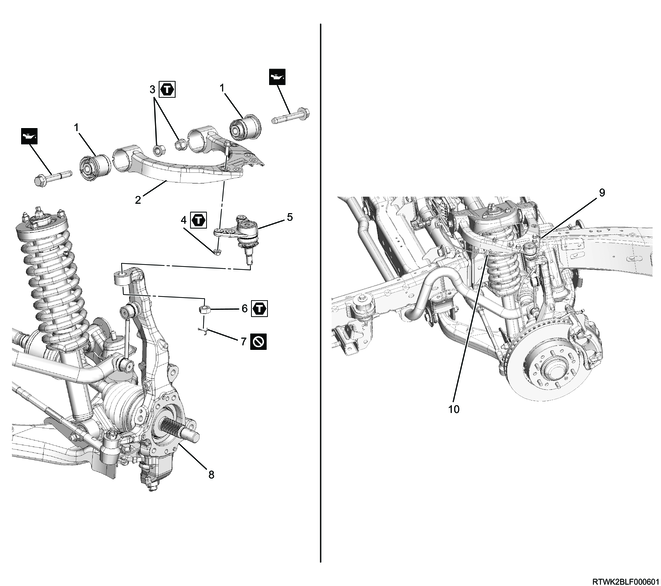
Upper link (2WD (Except high ride suspension specification))
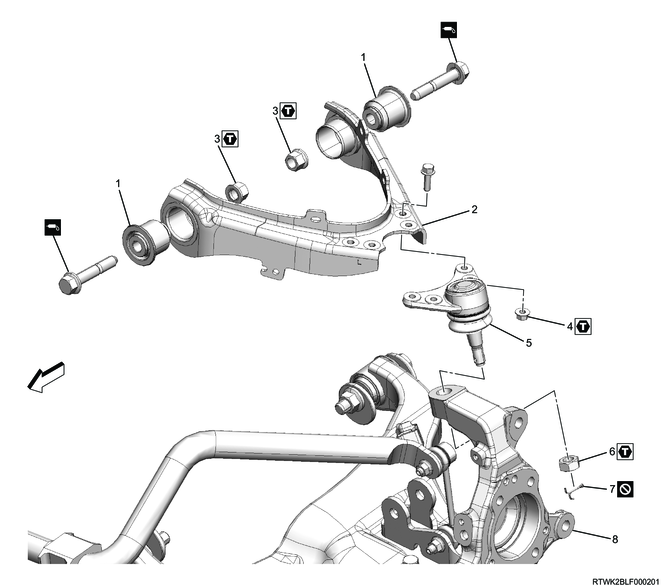
Part name
- Bushing
- Upper link
- Nut
- Nut
- Upper ball joint
- Nut
- Cotter pin
- Knuckle
Tightening torque
3: 137 N・m { 14.0 kgf・m / 101 lb・ft }
4: 31.4 N・m { 3.2 kgf・m / 23 lb・ft }
6: 98 N・m { 10.0 kgf・m / 72 lb・ft }
Lower link (2WD (Except high ride suspension specification))
Part name
- Cam bolt
- Bushing
- Lower link
- Cam plate
- Nut
- Shock absorber
- Stabilizer bar
- Nut
- Knuckle
- Nut
- Cotter pin
- Tie rod end
- Cotter pin
- Nut
- Lower ball joint
- Nut
- Nut
Tightening torque
5: 186 N・m { 19.0 kgf・m / 137 lb・ft }
8: 152 N・m { 15.5 kgf・m / 112 lb・ft }
10: 147 N・m { 15.0 kgf・m / 108 lb・ft }
14: 98 N・m { 10.0 kgf・m / 72 lb・ft }
16: 126.5 N・m { 12.9 kgf・m / 93 lb・ft }
17: 64 N・m { 6.5 kgf・m / 47 lb・ft }
Bumper rubber (2WD (Except high ride suspension specification))
Part name
- Bumper rubber
- Bolt
Tightening torque
2: 51 N・m { 5.2 kgf・m / 38 lb・ft }
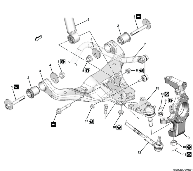
Shock absorber (2WD (High ride suspension specification), 4WD)
Part name
- Cam bolt
- Lower link
- Cam plate
- Nut
- Nut
- Nut
- Shock absorber assembly
- Knuckle
- Nut
- Cotter pin
- Nut
- Nut
- Stabilizer link
Tightening torque
4: 186 N・m { 19.0 kgf・m / 137 lb・ft }
5: 55 N・m { 5.6 kgf・m / 41 lb・ft }
6: 25 N・m { 2.5 kgf・m / 18 lb・ft }
9: 147 N・m { 15.0 kgf・m / 108 lb・ft }
11: 97.1 N・m { 9.9 kgf・m / 72 lb・ft }
12: 152 N・m { 15.5 kgf・m / 112 lb・ft }
Stabilizer bar (2WD (High ride suspension specification), 4WD)
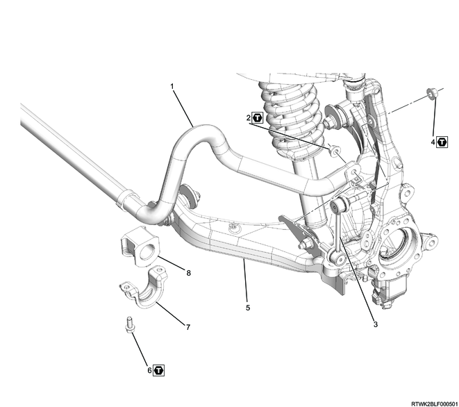
Part name
- Stabilizer bar
- Nut
- Stabilizer link
- Nut
- Lower link
- Bolt
- Clamp
- Rubber bushing
Tightening torque
2: 97.1 N・m { 9.9 kgf・m / 72 lb・ft }
4: 97.1 N・m { 9.9 kgf・m / 72 lb・ft }
6: 47.1 N・m { 4.8 kgf・m / 35 lb・ft }
Upper link (2WD (High ride suspension specification), 4WD)
Part name
- Bushing
- Upper link
- Nut
- Nut
- Upper ball joint
- Nut
- Cotter pin
- Knuckle
- Nut
- Clip
Tightening torque
3: 137 N・m { 14.0 kgf・m / 101 lb・ft }
4: 31.4 N・m { 3.2 kgf・m / 23 lb・ft }
6: 98 N・m { 10.0 kgf・m / 72 lb・ft }
Lower link (2WD (High ride suspension specification), 4WD)
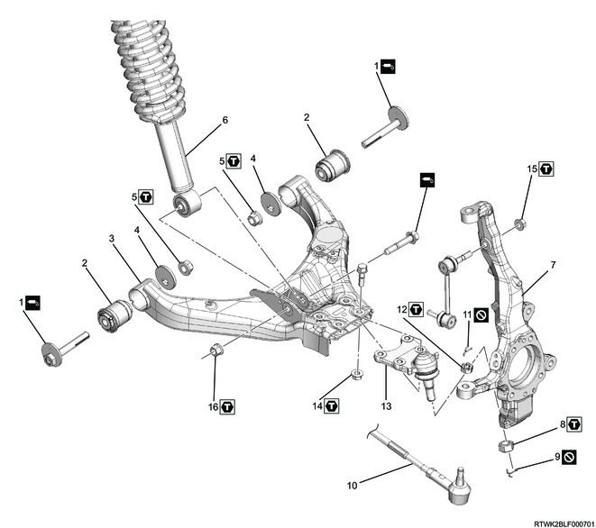
Part name
- Cam bolt
- Bushing
- Lower link
- Cam plate
- Nut
- Shock absorber
- Knuckle
- Nut
- Cotter pin
- Tie rod end
- Cotter pin
- Nut
- Lower ball joint
- Nut
- Nut
- Nut
Tightening torque
5: 186 N・m { 19.0 kgf・m / 137 lb・ft }
8: 147 N・m { 15.0 kgf・m / 108 lb・ft }
12: 98 N・m { 10.0 kgf・m / 72 lb・ft }
14: 126.5 N・m { 12.9 kgf・m / 93 lb・ft }
15: 97.1 N・m { 9.9 kgf・m / 72 lb・ft }
16: 152 N・m { 15.5 kgf・m / 112 lb・ft }
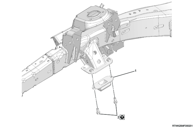
Bumper rubber (2WD (High ride suspension specification), 4WD)
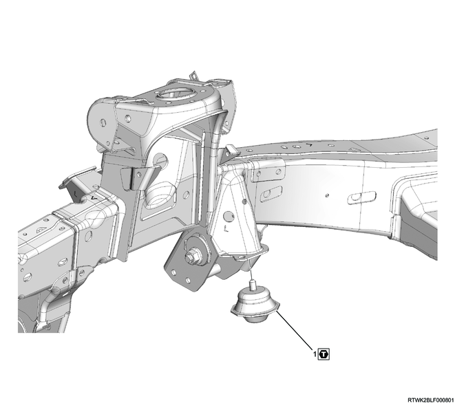
Part name
- Bumper rubber
Tightening torque
1: 106 N・m { 10.8 kgf・m / 78 lb・ft }
2. Independent suspension inspection
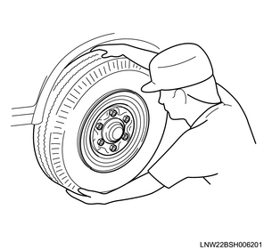
1. Disc wheel and tire inspection
1) Inspect for the following.
- Difference in left and right tire size
- Difference in left and right tire wear
- Cracking or damage on both sides and contact surface of the tire.
- Tire air pressure
- Does the disc wheel rotate smoothly?
- Is there abnormal noise from the disc wheel?
2) Measure the wheel runout.
Limit: 3.0 mm { 0.12 in }

2. Inspection of parts related to the front axle
1) Inspect for the following.
- Ball joint looseness
- Hub bearing looseness
- Knuckle arm looseness
- Kingpin looseness
3. Steering-related parts inspection
1) Inspect for the following.
- Looseness of each part
- Is there interference between the tire and other areas at the full lock angle?
- Does the knuckle hit the stopper at the full lock angle?
3. Preliminary and post procedures
1. Preliminary procedures
1) Open the engine hood.
2) Disconnect the battery cable from the battery negative terminal.
Caution
- After turning OFF the ignition switch (power mode for models with passive entry and start system), do not disconnect the battery cable within 3 minutes.
- If the battery cable is disconnected within 3 minutes, the vehicle electronic control system may malfunction.
- If the battery cable is disconnected, perform the setting of the front door power window switch with AUTO UP/AUTO DOWN function after connecting the battery negative terminal.
4. Disc wheel removal
1. Models with aluminum wheels
1) Move the vehicle to a flat surface.
2) Pull the parking brake lever.
3) Secure the vehicle using chock blocks.
4) Raise the vehicle.
Note
- Jack up the vehicle but not to an extent that the tire leaves the ground.
5) Remove the wheel cap from the disc wheel.
Note
- Insert a tool with flat tip such as a flathead screwdriver into the wheel cap groove to remove.
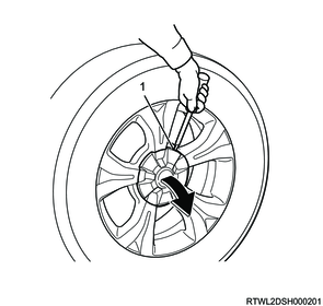
Legend
- Wheel cap groove
6) Loosen the wheel nuts.
Note
- Loosen without allowing the disc wheel to rattle.
Caution
- At this time, do not remove the wheel nuts.
7) Raise the vehicle.
Note
- Jack up the vehicle until the tire is completely off the ground.
- Support the frame using a chassis stand as necessary.
8) Remove the disc wheel from the vehicle.
2. Models with steel wheels
1) Move the vehicle to a flat surface.
2) Pull the parking brake lever.
3) Secure the vehicle using chock blocks.
4) Raise the vehicle.
Note
- Jack up the vehicle but not to an extent that the tire leaves the ground.
5) Remove the wheel cap from the disc wheel.
6) Loosen the wheel nuts.
Note
- Loosen without allowing the disc wheel to rattle.
Caution
- At this time, do not remove the wheel nuts.
7) Raise the vehicle.
Note
- Jack up the vehicle until the tire is completely off the ground.
- Support the frame using a chassis stand as necessary.
8) Remove the disc wheel and wheel cap from the vehicle.
5. Brake caliper removal
1) Remove the lock bolt from the brake caliper.
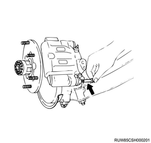
2) Remove the brake caliper from the brake support.
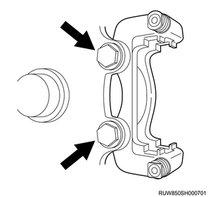
3) Remove the disc brake pad and shim from the brake support.
4) Remove the brake support from the knuckle.
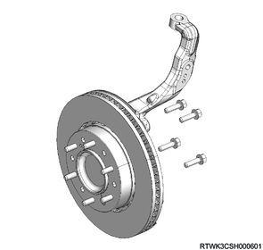
6. Front hub removal
1. 2WD (Except high ride suspension specifications)
1) Remove the bolt from the knuckle.
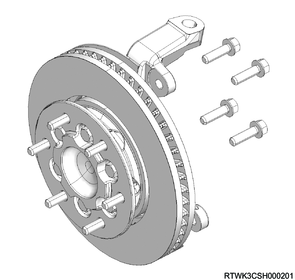
2) Remove the front hub and brake rotor from the knuckle.
3) Remove the knuckle cap from the knuckle.
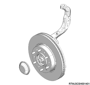
2. 2WD (High ride suspension specifications)
1) Remove the bolt from the knuckle.
2) Remove the front hub and brake rotor from the knuckle.
3) Remove the knuckle cap from the knuckle.
3. 4WD
1) Remove the hub cap from the front hub.
2) Remove the following parts from the front hub.
- Cotter pin
- Lock nut
- Washer
3) Remove the bolt from the knuckle.
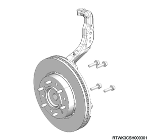
4) Remove the front hub and brake rotor from the knuckle.
7. Power steering unit disconnect
1) Remove the cotter pin from the ball joint.
2) Remove the castle nut from the ball joint.
3) Disconnect the tie rod end from the knuckle using the special tool.
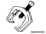
SST: 5-8840-2005-0 - ball joint remover
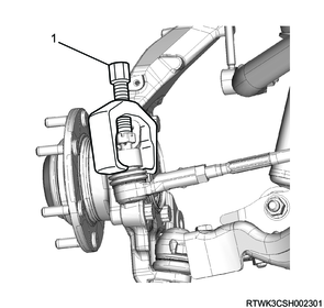
Legend
- 5-8840-2005-0
8. Wheel speed sensor removal
1. Precautions for wheel speed sensor removal
Caution
- Be careful not to damage the wheel speed sensor during service works, since it may cause ABS failure.
- Because ABS abnormalities or malfunctions may occur if the wheel speed sensor is improperly installed, follow the precautions detailed in the outlined procedure when installing, removing, or replacing the wheel speed sensor.
- When it is difficult to remove the wheel speed sensor body due to rust, use rust penetrant etc., and then carefully remove the sensor body by shifting it little by little until it comes free.
- Do not bump or step on the removed sensor.
- Do not remove the sensor unit by hammering.
- Do not insert a flat-head screwdriver or the like into the gap to remove it forcibly.
- Do not pull the sensor harness.
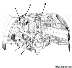
2. Removal (ABS-specification 2WD (Except high ride suspension specifications))
1) Disconnect the harness connector from the wheel speed sensor.
Legend
- Connector position
- Wheel speed sensor
- Harness bracket tightening nut
- Harness bracket tightening bolt
- Wheel speed sensor tightening bolt
2) Remove the harness bracket from the upper link and knuckle.
3) Remove the wheel speed sensor from the knuckle.
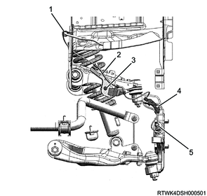
3. Removal (ABS-specification 2WD (High ride suspension specifications), ABS-specification 4WD)
1) Disconnect the harness connector from the wheel speed sensor.
2) Unlock the harness clips indicated by the arrows in the following diagram.
3) Remove the harness bracket from the upper link and knuckle.
4) Remove the wheel speed sensor from the knuckle.
Legend
- Connector position
- Wheel speed sensor
- Harness bracket tightening nut
- Harness bracket tightening bolt
- Wheel speed sensor tightening bolt
9. Dust cover removal
1) Remove the dust cover from the knuckle.
10. Stabilizer bar removal
1. 2WD (Except high ride suspension specifications)
1) Remove the stabilizer link from the stabilizer bar and lower link.
Caution
- Do not damage the ball joint boot.
2) Remove the clamp and stabilizer bar from the frame.
2. 2WD (High ride suspension specifications), 4WD
1) Remove the stabilizer link from the stabilizer bar and knuckle.
Caution
- Do not damage the ball joint boot.
2) Remove the clamp and stabilizer bar from the frame.
11. Knuckle removal
1. 2WD (Except high ride suspension specifications)
1) Disconnect the lower ball joint from the knuckle using the special tool.
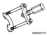
SST: 5-8840-2017-0 - ball joint remover
Caution
- Take care not to damage the ball joint boot.

Legend
- 5-8840-2017-0
2) Remove the knuckle from the upper ball joint using the special tool.
SST: 5-8840-2017-0 - ball joint remover
Caution
- Take care not to damage the ball joint boot.
Legend
- 5-8840-2017-0
2. 2WD (High ride suspension specifications)
1) Disconnect the lower ball joint from the knuckle using the special tool.
SST: 5-8840-2017-0 - ball joint remover
Caution
- Take care not to damage the ball joint boot.
Legend
- 5-8840-2017-0
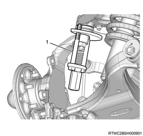
2) Remove the knuckle from the upper ball joint using the special tool.
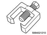
SST: 5-8840-2121-0 - upper ball joint remover
Caution
- Take care not to damage the ball joint boot.
Legend
- 5-8840-2121-0
3. 4WD
1) Disconnect the lower ball joint from the knuckle using the special tool.
SST: 5-8840-2017-0 - ball joint remover
Caution
- Take care not to damage the ball joint boot.
Legend
- 5-8840-2017-0
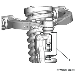
2) Remove the knuckle from the upper ball joint using the special tool.
SST: 5-8840-2121-0 - upper ball joint remover
Caution
- Take care not to damage the ball joint boot.
Legend
- 5-8840-2121-0
12. Upper link removal
1) Disconnect the brake hose from the upper link.
2) Remove the upper link from the frame.
13. Shock absorber removal
1) Disconnect the shock absorber from the lower link.
2) Remove the shock absorber from the frame.
14. Lower link removal
1) Place alignment marks on the cam bolt and suspension cross member.
2) Remove the lower link from the frame.
15. Bumper rubber removal
1) Remove the bumper rubber from the bracket.
16. Suspension cross member removal
1) Remove the suspension cross member from the frame.