1. ETM
1. Power supply
Power supply from the battery to each fuse is shown.
2. Fuse load
The equipment to which each fuse is related is shown.

3. Ground load
The equipment to which each ground is related is shown.
4. Individual equipment wiring diagram
The wiring information from each individual equipment fuse to ground is shown.
2. Location diagram
1. Internal circuit
The internal circuit of the J/B (Junction Block) is described.

2. Unit location diagram
Installation locations of each control unit, J/B (Junction Block), R/B (Relay Block), etc. are described.
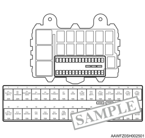
3. Fuse location diagram
Each fuse position is shown.
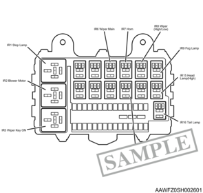
4. Relay location diagram
Each relay position is shown.
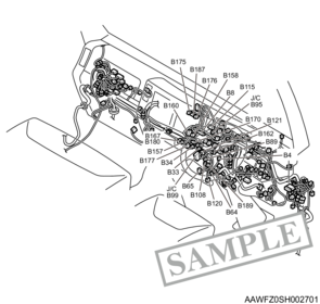
5. Connector location diagram
The locations of each connector are shown.
6. Ground location diagram
Each ground position is shown.

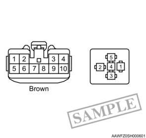
3. Connector list
1. Connector list/Relay list
The connector shape, terminal positions, and connector color (except for milky white color) are shown.
4. Descriptions in Wiring Diagram
1. Wiring information
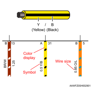
Wiring color and wire size are indicated.
The wiring colors are shown using color indications and color symbols.
The wire sizes are indicated using harness nominal sizes.
| Color symbol |
Color |
Color symbol |
Color |
| B |
Black |
LG |
Light green |
| W |
White |
GY |
Gray |
| R |
Red |
P |
Pink |
| G |
Green |
SB |
Sky blue |
| Y |
Yellow |
V |
Violet |
| L |
Blue |
T |
Tan |
| O |
Orange |
BE |
Beige |
| BR |
Brown |
A |
Lavender |
Example)
If 2 colors such as Y/B are shown, it means wiring with a black line on a yellow base.
| Nominal size |
Cross-sectional area (mm2) |
Outer diameter (mm) |
| 0.3 |
0.372 |
1.8 |
| 0.5 |
0.563 |
2.0 |
| 0.85 |
0.885 |
2.2 |
| 1.25 |
1.287 |
2.5 |
| 2 |
2.091 |
2.9 |
| 3 |
3.296 |
3.6 |
| 5 |
5.227 |
4.4 |
| 8 |
7.952 |
5.5 |
| 15 |
13.36 |
7.0 |
| 20 |
20.61 |
8.2 |
| Nominal size |
Cross-sectional area (mm2) |
Outer diameter (mm) |
| 0.13 |
0.1407 |
0.85 |
| 0.35 |
0.3436 |
1.1 |
| 0.5 |
0.4948 |
1.25 |
| 0.75 |
0.7266 |
1.4 |
| 1.25 |
1.247 |
1.8 |
| 2 |
1.964 |
2.55 |
| 3 |
2.976 |
3.05 |
| Nominal size |
Cross-sectional area (mm2) |
Outer diameter (mm) |
| 0.75 |
0.7266 |
1.4 |
| 1 |
0.9852 |
1.6 |
| 1.25 |
1.247 |
1.8 |
| 1.5 |
1.539 |
1.85 |
Note
- Please refer to the wiring repair precaution page.
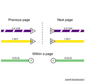
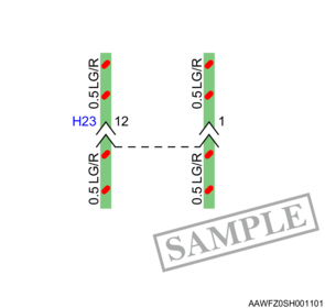
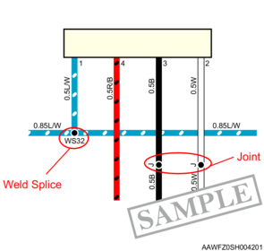
2. Wiring connection symbols
Shows that the wiring with the same symbol is connected.
3. Connector
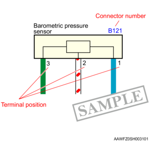
(a) Connector number
When multiple wires connected to equipment (a component) exist within the same connector, the connector number is indicated either inside or outside the equipment, and the corresponding terminal position is indicated next to each wire.
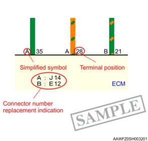
When multiple connectors are connected to a component, each connector number is expressed on the wiring diagram with a replacing simplified symbol.
Example)
A: J14 means that the J14 connector is indicated by the substitute simplified symbol A.
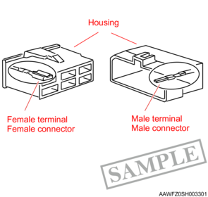
(b) Intermediate connector
Connectors that are connecting wires are indicated.
The groove side indicates female side connector, and the protruding side indicates male side connector.
On the wiring diagram, when connectors are linked with a dashed line (----), it means that they are the same connector.
(c) Connector shape and terminal shape
- Female connector………Indicates that the terminals are female.
- Male connector………Indicates that the terminals are male.
(d) Joint connector
A connector in which multiple terminals are collectively connected using joint terminals is indicated.
Alphabets indicate jointed groups (collectively connected terminals).

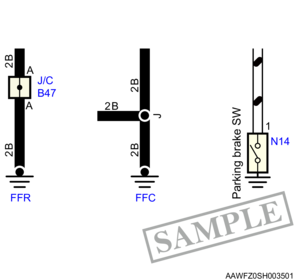
4. Ground point
Ground positions are described using symbols.
Example)
FFR = Frame front right
FFC = Frame front center
For the parking brake SW, etc., it indicates that a chassis ground is used (the switch itself is connected to a ground).
5. Fuse
Fuse numbers, names, capacities, and energizing conditions (in parentheses) are shown.
Example)
(IG) = Ignition switch energized with IG
(TAIL) = Lighting switch energized with ON
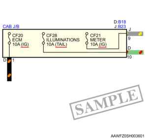
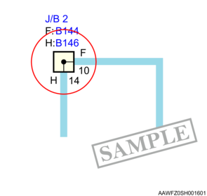
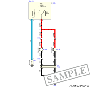
6. Junction block
Internal connections within a junction block which is related to each circuit are indicated.
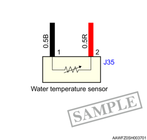
7. Component
Components are shown as frames (yellow inside), and the name of the component is shown either inside or outside the frame.
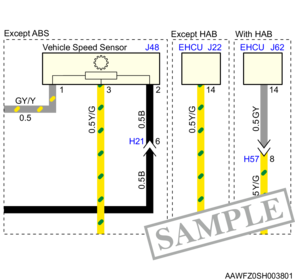
8. Descriptions of specification differences
Differences in wiring diagram due to specification are indicated in a dashed border.
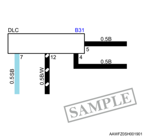
9. External connector
External connectors (DLC, service connectors, etc.), body modification parts, locally procured parts are represented as a frame (white inside).
10. Wiring not described
This document describes connections between the vehicle wire harness and each component. Therefore, connections made between components that do not pass through the vehicle wire harness are not described.

11. Relay
Relay numbers, relay names, and relay internal circuits are shown.
1) If the relay is not completed in the relevant circuit, a line is added to the connection terminal and the referenced circuit names are indicated on the circuit diagram.
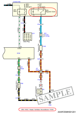
【Relay operation example】
When the horn switch (FL4) is pressed, current flows through pin 3 and pin 5 in the relay, and the coil in the relay is energized.
The contact point is moved by electromagnetism after the coil is energized, and pin 1 and pin 2 are connected.
When pin 1 and pin 2 are connected, power is supplied to the horn, and the horn sounds.
When the horn switch is disconnected, excitation in the coil ceases, the contact points are returned to the original status, pin 1 and pin 2 are disconnected (pin 1 and pin 4 are connected), and the horn stops sounding.
12. Control unit (C/U)
Signal names are indicated on the terminals inside the control unit illustrations.
The meaning of the signal names are indicated below.
| Signal name |
Meaning |
| 24 V |
Battery voltage |
| 5 V |
Device voltage |
| GND |
Ground |
| SIG |
Signal input |
| CONT |
Coil, LED drive |
| DRIVE |
Motor drive |
| U, V, W |
Three-phase motor drive |
| CAN-L |
CAN-LOW signal |
| CAN-H |
CAN-HIGH signal |

13. Joint, weld splice
If the wiring is joined, the weld splice number is shown on the weld splice and joint terminal, and J is shown at the joint.
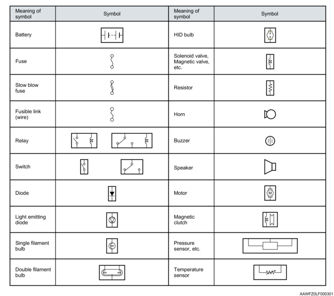
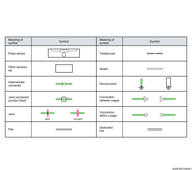
14. Circuit symbols
15. Abbreviations
| Abbreviations |
Explanation |
Abbreviations |
Explanation |
| # |
Cylinder or number indicator |
FFR |
Frame Front Right |
| CAB |
Cab |
Fr |
Front |
| CBL |
Cab Back Left |
FSL |
Frame Side Left |
| CBR |
Cab Back Right |
FSR |
Frame Side Right |
| CFC |
Cab Front Center |
HBL |
Hybrid unit Box Lower |
| CFL |
Cab Floor Left |
HBM |
Hybrid unit Box Middle |
| CFR |
Cab Floor Right |
HBU |
Hybrid unit Box Upper |
| CHASS |
Chassis |
Hi |
High |
| CSD |
Cold Start Device |
L/H |
Left Hand |
| E/B |
Electric Box |
Lo |
Low |
| EBL |
Engine Block Left |
P/W |
Power Window |
| ECL |
Engine Compartment Left |
R/B |
Relay Box |
| ECR |
Engine Compartment Right |
R/H |
Right Hand |
| EHL |
Engine Head Left |
RL |
Relay |
| FCB |
Frame Center Battery |
S/B |
Switch Box |
| FFC |
Frame Front Center |
VGS |
Variable Geometry System |
| FFL |
Frame Front Left |