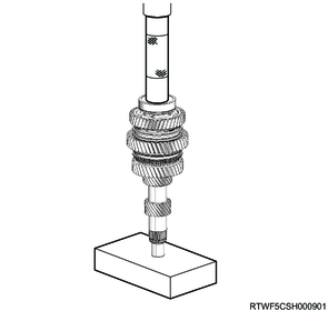
1. Component views
Main shaft
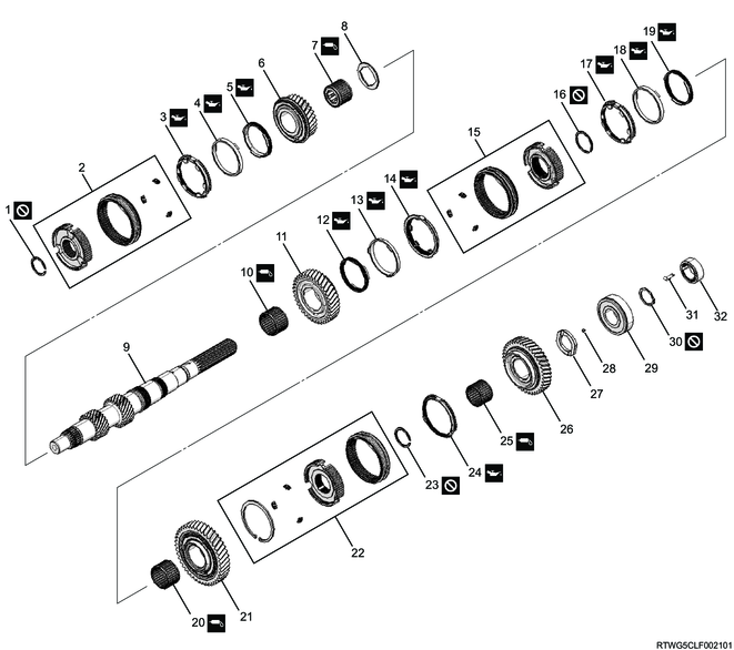
Part name
- Snap ring
- 3rd - 4th synchronizer
- 3rd block ring
- 3rd outside ring
- 3rd inside ring
- 3rd gear
- Needle bearing
- Thrust washer
- Main shaft
- Needle bearing
- 2nd gear
- 2nd inside ring
- 2nd outside ring
- 2nd block ring
- 1st - 2nd synchronizer
- Snap ring
- 1st block ring
- 1st outside ring
- 1st inside ring
- Needle bearing
- 1st gear
- Reverse synchronizer
- Snap ring
- Reverse block ring
- Needle bearing
- Reverse gear
- Thrust washer
- Ball
- Main shaft rear bearing
- Snap ring
- Gear set clip (2WD, models without ABS)
- Speedometer drive gear (2WD, models without ABS)
2. 2nd gear installation
1) Apply the grease to the needle bearing.
2) Install the needle bearing to the main shaft.
3) Apply the recommended lubricating oil to the 2nd gear inner surface.
4) Install the 2nd gear to the main shaft.
5) Apply gear oil to the following parts, and install to the 2nd gear.
- 2nd block ring
- 2nd outside ring
- 2nd inside ring
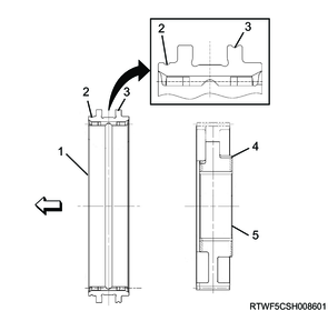
6) Assemble the 1st - 2nd synchronizer.
Note
- Install the insert and sleeve to the 1st - 2nd clutch hub.
- Install with the sleeve identification groove for installation direction facing toward the transmission front.
- The 1st - 2nd clutch hub has no front or rear directions.
Caution
- Check the 1st -2nd synchronizer sleeve identification grooves shown in the diagram, and install the sleeve to the 1st - 2nd clutch hub.
- Pay attention not to mistakenly assemble the reverse synchronizer sleeve or 3rd - 4th synchronizer sleeve.
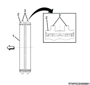
Legend
- Sleeve
- Identification groove for installation direction
- Identification groove for 1st - 2nd synchronizer sleeve
Note
- Make sure the clutch hub and sleeve slide smoothly.
7) Press-fit the 1st - 2nd synchronizer to the main shaft using the special tool.
Caution
- Inspect the entire circumference to check whether the ring is riding up.
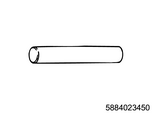
SST: 5-8840-2345-0 - Installer
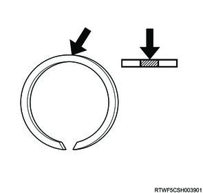
8) Select the snap ring that creates the minimum clearance between the clutch hub and the snap ring.
Caution
- Do not reuse the snap ring.
| Snap ring thickness |
Identification color |
| 1.9 mm { 0.075 in } |
Green |
| 2.0 mm { 0.079 in } |
White |
3. 1st gear installation
1) Apply gear oil to the following parts, and install to the 1st - 2nd clutch hub.
- 1st block ring
- 1st outside ring
- 1st inside ring
2) Apply the grease to the needle bearing.
3) Install the needle bearing to the main shaft.
4) Apply the recommended lubricating oil to the 1st gear inner surface.
5) Install the 1st gear to the main shaft.
4. Reverse gear installation
1) Assemble the reverse synchronizer.
Note
- Install the following parts to the reverse clutch hub.
- Snap ring
- Sleeve
- Insert
Caution
- Make sure that the snap ring opening does not overlap the insert.
Note
- Install with the identification groove for sleeve installation direction facing toward the 1st gear side.
Caution
- Install with the longer section of the reverse clutch hub boss facing toward the reverse gear side.
- Check that there is no identification groove for sleeve in the section indicated with the arrow in the diagram, and install the sleeve to the reverse clutch hub.
- Pay attention not to mistakenly assemble the 1st - 2nd synchronizer sleeve or 3rd - 4th synchronizer sleeve.
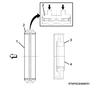
Legend
- Sleeve
- Identification groove for installation direction
- Boss section
- Reverse clutch hub
2) Press-fit the reverse synchronizer to the main shaft using the special tool.
SST: 5-8840-2345-0 - Installer

3) Select the snap ring that creates the minimum clearance between the clutch hub and the snap ring.
Caution
- Do not reuse the snap ring.
| Snap ring thickness |
Identification color |
| 1.9 mm { 0.075 in } |
LT GRN |
| 2.0 mm { 0.079 in } |
Blue |
4) Apply gear oil to the reverse block ring, and install it to the reverse clutch hub.
5) Apply the grease to the needle bearing.
6) Install the needle bearing to the main shaft.
7) Apply the recommended lubricating oil to the reverse gear inner surface.
8) Install the reverse gear to the main shaft.
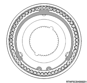
9) Install the ball to the main shaft.
Legend
- Needle bearing
- Reverse gear
- Ball
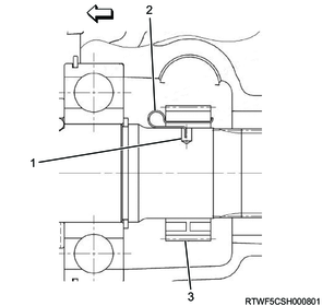
10) Press-fit the thrust washer to the main shaft using the special tool.
Note
- The thrust washer has no front or rear directions.
- Align the thrust washer groove indicated in the diagram to the ball installed to the main shaft, and press-fit the thrust washer to the main shaft.
Caution
- The force of the pressure to the thrust washer should not exceed 19,600 N {1,999 kg / 4,406 lb}.
SST: 5-8840-2345-0 - Installer
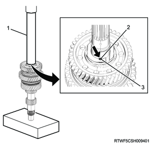
Legend
- 5-8840-2345-0
- Ball
- Thrust washer groove
11) Press-fit the main shaft rear bearing to the main shaft using the special tool.
Caution
- Face the snap ring groove side toward the transmission front.

SST: 5-8840-2244-0 - bearing installer
12) Install the snap ring to the main shaft using snap ring pliers.
Note
- Select a snap ring that will leave the minimum clearance between the main shaft rear bearing and the snap ring.
Caution
- Do not reuse the snap ring.
| Snap ring thickness |
Identification color |
| 1.75 mm { 0.0689 in } |
Pink |
| 1.85 mm { 0.0728 in } |
Amber |
| 1.95 mm { 0.0768 in } |
Purple |
5. Speedometer drive gear installation
1. 2WD models (Models without ABS)
1) Install the gear set clip to the speedometer drive gear.
Caution
- Do not mistake the assembly direction of the gear set clip.
2) Install the speedometer drive gear to the output shaft.
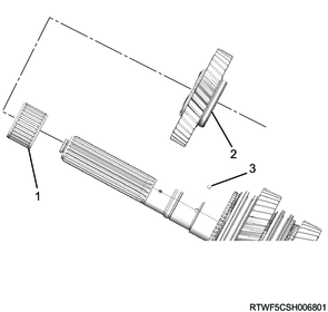
Legend
- Output shaft
- Gear set clip
- Speedometer drive gear
6. 3rd gear installation
1) Install the thrust washer to the main shaft.
2) Apply the grease to the needle bearing.
3) Install the needle bearing to the main shaft.
4) Apply the recommended lubricating oil to the 3rd gear inner surface.
5) Install the 3rd gear to the main shaft.
6) Apply gear oil to the following parts, and install to the 3rd gear.
- 3rd block ring
- 3rd outside ring
- 3rd inside ring
7) Assemble the 3rd - 4th synchronizer.
Note
- Install the insert and sleeve to the 3rd - 4th clutch hub.
- Make sure the clutch hub and sleeve slide smoothly.
- Install with the sleeve identification groove for installation direction facing toward the transmission front.
Caution
- Check the 3rd - 4th synchronizer sleeve identification groove shown in the diagram, and install the sleeve to the 3rd - 4th clutch hub.
- Pay attention not to mistakenly assemble the reverse synchronizer sleeve or 1st - 2nd synchronizer sleeve.
Legend
- Sleeve
- Identification groove for installation direction
- Identification groove for 3rd - 4th synchronizer sleeve
- Boss section
- Clutch hub
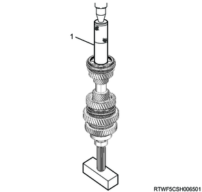
8) Press-fit the 3rd - 4th synchronizer to the main shaft using the special tool.
Note
- Face the surface with the oil groove toward the 3rd gear side.
Caution
- Inspect the entire circumference to check whether the ring is riding up.
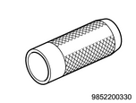
SST: 9-8522-0033-0 - gear installer
Legend
- 9-8522-0033-0
9) Install the snap ring to the main shaft using snap ring pliers.
Caution
- Do not reuse the snap ring.