1. Component views
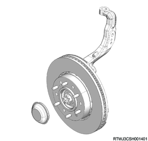
Front hub and disc rotor (2WD (Except high ride suspension specifications))
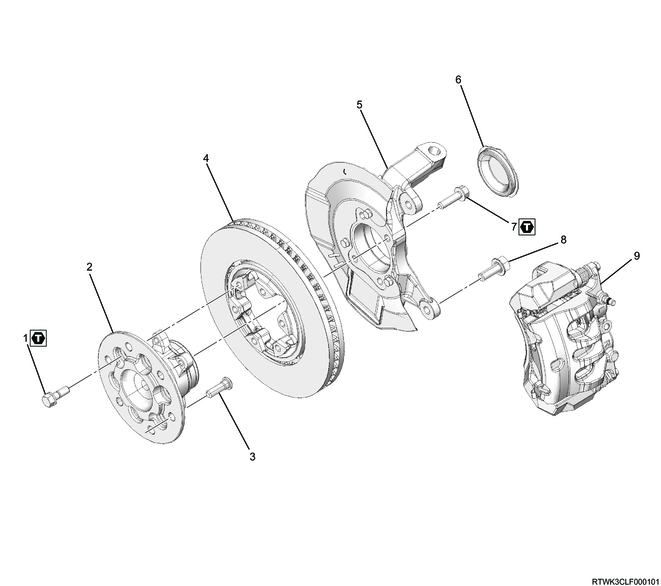
Part name
- Bolt
- Hub
- Wheel pin
- Brake disc
- Knuckle and dust cover
- Knuckle cap
- Bolt
- Bolt
- Brake caliper
Tightening torque
1: 93 to 113 N・m { 9.5 to 11.5 kgf・m / 69 to 83 lb・ft }
7: 85 N・m { 8.7 kgf・m / 63 lb・ft }
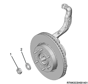
Front hub and disc rotor (2WD (High ride suspension specifications))
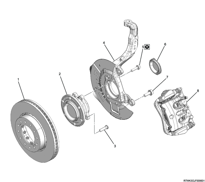
Part name
- Brake rotor
- Hub
- Wheel pin
- Knuckle and dust cover
- Bolt
- Knuckle cap
- Bolt
- Brake caliper
Tightening torque
5: 85 N・m { 8.7 kgf・m / 63 lb・ft }
Front hub and disc rotor (4WD)

Part name
- Brake disc
- Hub cap
- Cotter pin
- Lock nut
- Washer
- Hub
- Knuckle and dust cover
- Bolt
- Bolt
- Brake caliper
- Wheel pin
Tightening torque
4: 127 N・m { 13.0 kgf・m / 94 lb・ft }
8: 85 N・m { 8.7 kgf・m / 63 lb・ft }
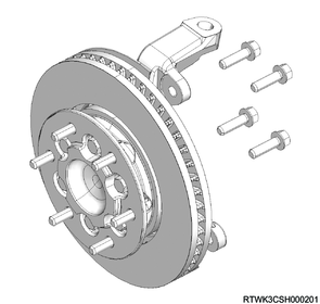
2. Front hub installation
1. 2WD (Except high ride suspension specifications)
1) Install the knuckle cap to the knuckle.
2) Install the front hub and brake rotor to the knuckle.
3) Install the bolt to the knuckle.
Tightening torque: 85 N・m { 8.7 kgf・m / 63 lb・ft }
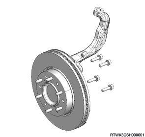
2. 2WD (High ride suspension specifications)
1) Install the knuckle cap to the knuckle.
2) Install the front hub and brake rotor to the knuckle.
3) Install the bolt to the knuckle.
Tightening torque: 85 N・m { 8.7 kgf・m / 63 lb・ft }
3. 4WD
1) Install the front hub and brake rotor to the knuckle.
2) Install the bolt to the knuckle.
Tightening torque: 85 N・m { 8.7 kgf・m / 63 lb・ft }
3) Install the washer and lock nut to the front hub.
Tightening torque: 127 N・m { 13.0 kgf・m / 94 lb・ft }
Legend
- Lock nut
- Washer
4) Install the cotter pin to the front hub.
Caution
- If the cotter pin hole position does not align, rotate the lock nut in the tightening direction to align it.
5) Install the hub cap to the front hub.
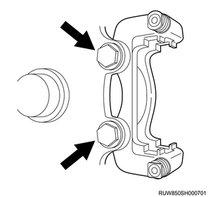
3. Brake caliper installation
1) Install the brake support to the knuckle.
Tightening torque: 205 to 245 N・m { 20.9 to 25.0 kgf・m / 151 to 181 lb・ft }
2) Install the disc brake pad and shim to the brake support.
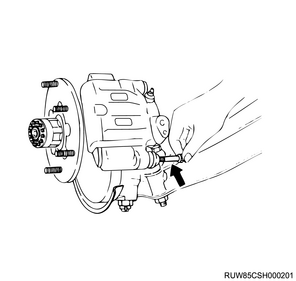
3) Install the brake caliper to the brake support.
4) Install the lock bolt to the brake caliper.
Tightening torque: 32 to 42 N・m { 3.3 to 4.3 kgf・m / 24 to 31 lb・ft }
4. Disc wheel installation
1. Models with aluminum wheels
1) Temporarily tighten the disc wheel to the vehicle.
2) Lower vehicle.
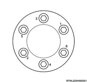
3) Final tighten the wheel nut in the order shown in the diagram.
Tightening torque: 120 N⋅m {12 kgf⋅m / 87 lb⋅ft}
Caution
- After completing installation, make sure to further tighten the wheel nuts to the specified torque after the vehicle has been driven a distance exceeding the standard value.
Standard: 50 to 100 km { 31 to 62 mile }
4) Install the wheel cap to the disc wheel.
Note
- For models with 18-inch aluminum wheels, align the wheel cap groove with the air valve before installing.
5) Check that the surfaces of the wheel cap and wheel are flat.
Note
- If the surfaces are not flat, the wheel cap may fall off.
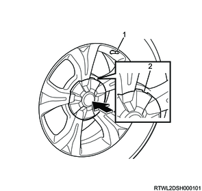
Legend
- Valve
- Wheel cap groove
2. Models with steel wheels
1) Temporarily tighten the disc wheel and wheel cap to the vehicle.
2) Lower vehicle.
3) Final tighten the wheel nut in the order shown in the diagram.
Tightening torque: 120 N⋅m {12 kgf⋅m / 87 lb⋅ft}
Caution
- After completing installation, make sure to further tighten the wheel nuts to the specified torque after the vehicle has been driven a distance exceeding the standard value.
Standard: 50 to 100 km { 31 to 62 mile }