1. Component views
Cylinder head
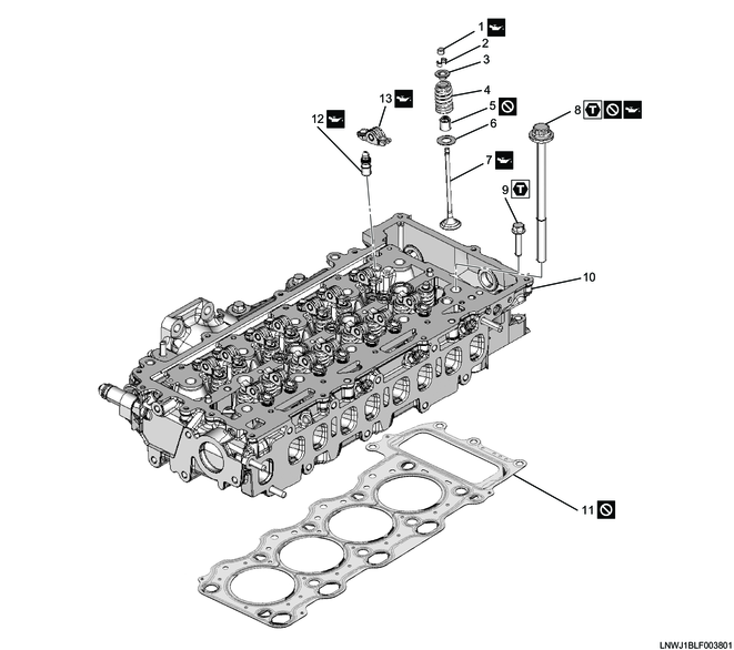
Part name
- Valve stem end cap
- Split collar
- Spring upper seat
- Valve spring
- Valve stem oil seal
- Spring lower seat
- Valve
- Cylinder head bolt
- Bolt
- Cylinder head
- Cylinder head gasket
- HLA
- Rocker arm
Tightening torque
8-1: 115 N・m { 11.7 kgf・m / 85 lb・ft }
8-2: 115 N・m { 11.7 kgf・m / 85 lb・ft }
8-3: 90 to 120 °
8-4: 90 to 120 °
9: 25 N・m { 2.5 kgf・m / 18 lb・ft }
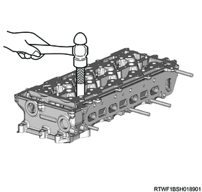
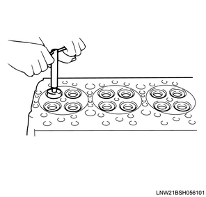
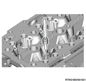
2. Valve guide installation
1) Tap in the valve guide from the top of the cylinder head to the standard depth using the special tool.
Caution
- When replacing the valve guide, replace as a set with the valve.
Standard: 9.80 to 10.20 mm { 0.3858 to 0.4016 in } Height from the cylinder head top surface to the valve guide end face
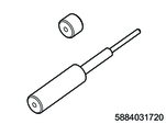
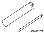
SST: 5-8840-3172-0 - valve guide remover and installer
2) Adjust the valve guide inner diameter to the standard value using a reamer.
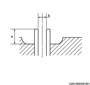
Legend
a. Height from the cylinder head top surface to the valve guide end surface
Standard value
b: 5.500 to 5.515 mm { 0.2165 to 0.2171 in } Valve guide inner diameter
3. Valve seat insert installation
1) Put the dolly block on the valve seat insert.
Note
- Carefully place a dolly block having an outer diameter smaller than the valve seat insert on top of the valve seat insert.
Caution
- Check for foreign material or scratches on the press-fitting surface of the cylinder head valve seat insert.
2) Install the valve seat insert to the cylinder head using a press.
Note
- Gradually apply pressure to the dolly block and push in the valve seat insert.
Caution
- Do not apply excessive pressure with the press.
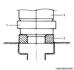
Legend
- Dolly block
- Valve seat insert
- Press
3) Adjust the valve seat to the standard value using a seat cutter.
Note
- Minimize scratches and other uneven sections to adjust the contact width to the specified value.
Caution
- Get rid of only the scratches and uneven portions, but be careful not to over-cut.
- Use an adjustable valve cutter pilot.
- The valve cutter pilot should not be allowed to scrape inside the valve guide.
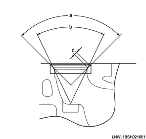
Standard value
a: 90 ° Angle 1, inlet valve
a: 90 ° Angle 1, exhaust valve
b: 48 ° Angle 2, inlet valve
b: 60 ° Angle 2, exhaust valve
c: 1.5 mm { 0.059 in } Contact width
4) Apply the compound to the valve seat surface.
5) Fit the valve by turning and lightly tapping.
Caution
- Confirm that there is even contact around the entire circumference.
- After fitting, completely remove the compound.

4. Valve stem oil seal installation
1) Install a lower spring seat to the cylinder head.
2) Apply engine oil to the valve guide outer circumference.
3) Install the valve stem oil seal to the special tool.
SST: 5-8840-3173-0 - valve stem seal installer
4) Install the valve stem oil seal to the cylinder head using the special tool.
Caution
- Do not reuse the valve stem oil seal.
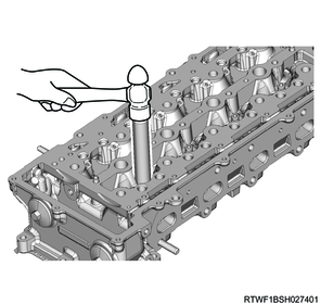
5) Inspect for the following.
- Is the valve stem oil seal correctly inserted?
- Is it slanted?
- Whether the garter spring is removed
5. Valve installation
1) Apply engine oil to the valve stems of the inlet valve and exhaust valve.
2) Install the inlet valve and the exhaust valve to the cylinder head.
Caution
- Install the valve so that there is no rubber detaching or scratches.
6. Valve spring installation
1) Install the valve spring to the cylinder head.
2) Install the spring upper seat to the valve spring.
3) Install the split collar to the valve using the special tool.

SST: 5-8840-3171-0 - valve spring compressor
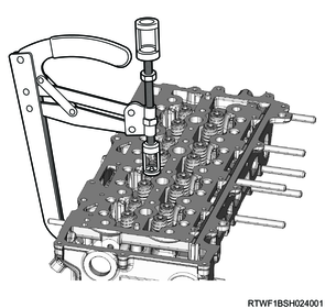
4) Move the valve spring up and down to check that it moves smoothly.
5) Apply engine oil to the valve stem end cap and valve stem end.
6) Install the valve stem end cap to the valve stem.
7. HLA installation
1) Install the HLA to the cylinder head.
Caution
- Install while taking care not to allow the HLA inner oil to spill out.
- Check for foreign material or sludge on the HLA mounting hole of the cylinder head.

Legend
- HLA
- Cylinder head
2) Apply engine oil to the HLA.
Note
- Apply oil until the hole at the top of the HLA is filled.
8. Rocker arm installation
1) Apply engine oil to the tip of the HLA and the end surface of the valve stem end cap.
2) Install the rocker arm to the HLA and valve stem end cap.

Legend
- Rocker arm
- Valve stem end cap
- HLA
3) Apply engine oil to the rocker arm roller section.
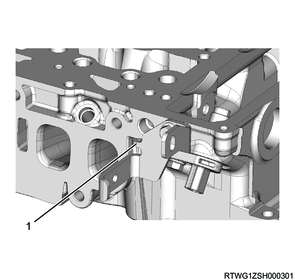
9. CMP sensor installation
1) Apply soapy water to the O-ring.
2) Install the CMP sensor to the cylinder head.
Tightening torque: 5.0 N・m { 0.51 kgf・m / 44.3 lb・in }
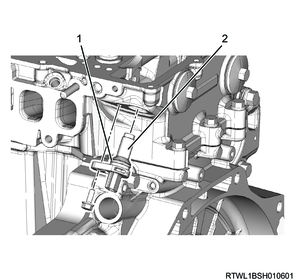
Legend
- O-ring
- CMP sensor
3) Install the fuel pipe bracket to the cylinder head.
Note
- Install so that the fuel pipe bracket detent makes contact with the cylinder head indentation.
Tightening torque: 10.0 N・m { 1.0 kgf・m / 89 lb・in }
Legend
- Detent