1. Final drive inspection
1) Inspect each bearing for the following.
- Seizing
- Spalling
- Noise
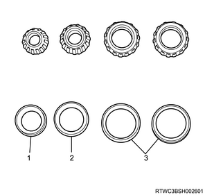
Legend
- Inner bearing
- Outer bearing
- Side bearing
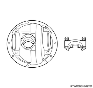
2) Inspect the differential carrier rear axle mounting section, differential carrier side bearing mounting section, as well as bearing cap for the following.
- Cracking
- Damage
- Wear
3) Inspect the pinion bearing race and pinion bearing oil seal inlay sections for the following.
- Cracking
- Damage
- Wear
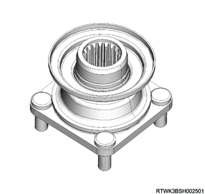
4) Inspect the flange for the following.
- Worn oil seal contact section
- Worn spline section
- Cracking of mounting section
- Damage to the mounting section
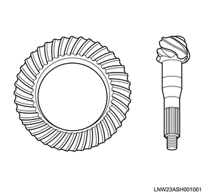
5) Inspect the gear contact surfaces on the drive and coast sides of the ring gear and drive pinion for the following.
- Chipping
- Cracking
- Spalling
- Pitting
- Improper tooth contact
6) Inspect the spline section of the drive pinion for the following.
- Cracking
- Twisting
- Damage
Caution
- Replace the ring gear and drive pinion as a set.
2. Differential cage inspection
1. Visual inspection
1) Inspect the differential cage for the following.
- Wear
- Damage
- Corrosion
- Other malfunctions
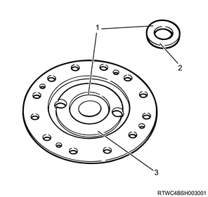
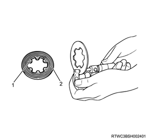
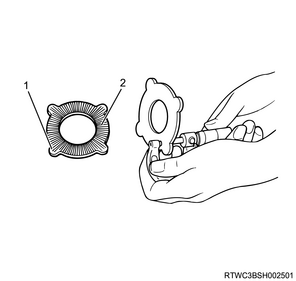
2) Inspect the friction disc, friction plate, and spring plate for the following.
- Wear
- Damage
- Abnormal noise
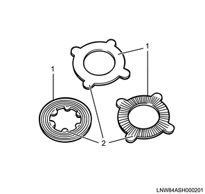
Legend
- Friction sliding surface
- Protrusion
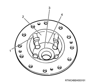
3) Inspect the following sections of the pressure ring for damage or other abnormal conditions.
- Sliding surface of the pressure ring and friction disc
- Sliding surface of the pressure ring inner surface and pinion gear
- Sliding surface of the pressure ring hole and side gear
- Sliding surface of the pressure ring and drive pinion
- Mating surface of the pressure ring and differential cage A
- Pressure ring and differential cage sliding surface
Note
- If there are dents or damage on the pressure ring and friction sliding surface, repair using an oil stone and compound.
- If there are minor burrs and dents on the pressure ring and differential cage sliding surface, repair using an oil stone.
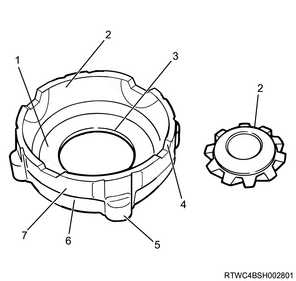
Legend
- Sliding surface of the pressure ring and side gear
- Sliding surface of the pressure ring inner surface and pinion gear
- Sliding surface of the pressure ring hole and side gear
- Sliding surface of the pressure ring and drive pinion
- Mating surface with differential cage A
- Friction disc sliding surface
- Pressure ring and differential cage sliding surface
4) Inspect the following sections of the side gear thrust washer for damage or other abnormal conditions.
- Sliding surface of the pressure ring and side gear
- Sliding surface between the side gear and the thrust washer
- Sliding surface of the pressure ring and drive pinion
- Sliding surface of the pressure ring hole and side gear
- Burrs on the denting section around the side gear
Note
- Repair minor burrs and dents around the side gear using an oil stone.
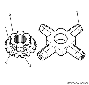
Legend
- Sliding surface of the pressure ring and side gear
- Sliding surface between the side gear and the thrust washer
- Sliding surface of the pressure ring and spider
- Sliding surface of the pressure ring hole and side gear
- Burrs on the denting section around the side gear
5) Inspect the following sections of the differential cage for damage or other abnormal conditions.
- Contact surface of the differential cage and thrust washer
- Contact surface of the differential cage and spring plate
Legend
- Contact surface of differential cage A and the thrust washer
- Sliding surface of the side gear and thrust washer
- Contact surface of differential cage A and the spring plate
Legend
- Mating surface of differential cage A and differential cage A
- Sliding surface of the pressure ring and differential cage B
- Contact surface of differential cage B and the thrust washer
- Contact surface of differential cage B and the spring plate
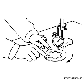
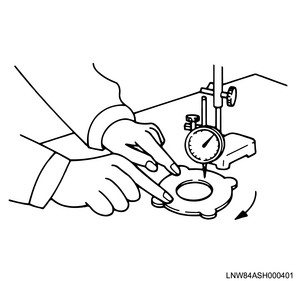
2. Friction disc and friction plate measurement
1) Measure the deformation of the friction disc and friction plate using a dial gauge.
Limit: 0.08 mm { 0.003 in }
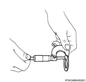
2) Measure the wear of the friction disc and friction plate using a micrometer.
Limit: 0.1 mm { 0.004 in }
Legend
- Protrusion
- Friction sliding surface
Legend
- Protrusion
- Friction sliding surface
3. Side gear thrust washer measurement
1) Measure wear of the side gear thrust washer using a micrometer.
Limit: 1.3 mm { 0.05 in }