1. Starter motor inspection
1. Cleaning
1) Clean all the disassembled parts.
Caution
- Be careful not to allow the solvent enter the clutch assembly or sealed bearing.
- Do not use solvent when cleaning the armature bearing.
- Make sure to use a cleaner for electronic parts to clean the following parts.
- Solenoid coil
- Brush
- Armature
2. Visual inspection
1) Inspect the starter housing for the following.
- Is there no crack or damage in the housing?
- Is there any symptom of bearing spins in the clutch bearing bore?
- Is the flange surface flat?
- Is the housing worn?
Note
- Replace the starter housing if any abnormal conditions are found.
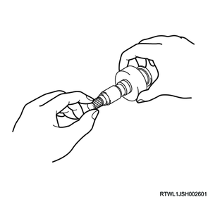
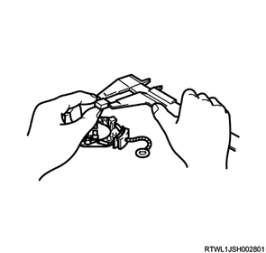
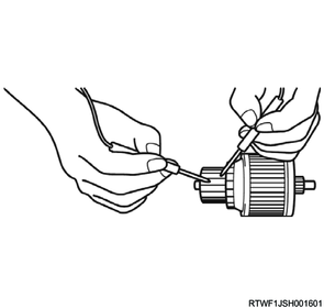
2) Inspect the overrunning clutch.
Note
- By rotating the pinion with a hand while holding the overrunning clutch housing section with the other hand, the pinion is slowly rotated in one direction with a certain resistance. However, it is not rotated in the opposite direction. If this does not occur, replace the overrunning clutch.
- Inspect the pinion, and replace the pinion if it is damaged or worn.
Caution
- The inside of the overrunning clutch is filled with grease. If it is washed using wash oil or oil removing detergents, the grease may be washed out of it. Therefore, simply wipe off any dirt from the overrunning clutch with a cloth.
3) Inspect the clutch gear and shaft bearing section for wear.
4) Inspect the needle bearing, rear bearing, and planetary gear for wear.
5) Inspect the magnetic switch for cracks or other damage.
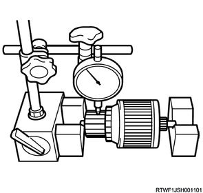
6) Inspect the armature.
Note
- If the commutator runout is larger than 0.05 mm {0.002 in}, replace the armature.
7) Inspect the commutator segment for wear or damage.
Caution
- The depth of each segment must not be less than 0.05 mm {0.002 in}.
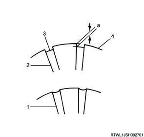
Legend
- Incorrect
- Correct
- Insulator
- Commutator segment
Limit
a: 0.05 mm { 0.002 in }
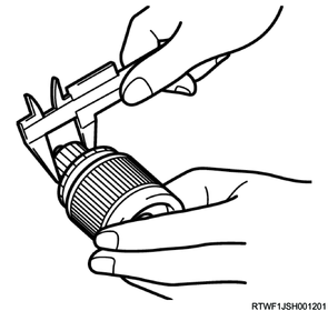
8) Measure the outer diameter of the commutator.
Caution
- The diameter must not be less than 28.9 mm {1.14 in}.
9) Inspect the armature bearing for wear or damage.
Caution
- If abnormal sound is heard while rotating the bearing by hand, the bearing must be replaced.
10) Inspect the brush and brush holder.
Note
- If the brush length is less than 5 mm {0.2 in}, replace the brush.
11) Inspect the brush spring for wear, damage, or other abnormal conditions.
Note
- If the brush does not smoothly move in the brush holder, check the brush holder for deformation, sliding surface, or dirt. Clean or repair as necessary.
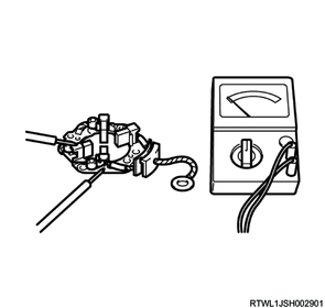
12) Apply one probe of an ohmmeter or self-powered test light to the positive (+) side of the insulated brush holder, and the other probe to the negative (-) side of the grounder brush holder.
Note
- If the light illuminates or an ohmmeter indicates continuity, the brush holder is grounded and must be replaced.
3. Electric bench test (Starter)
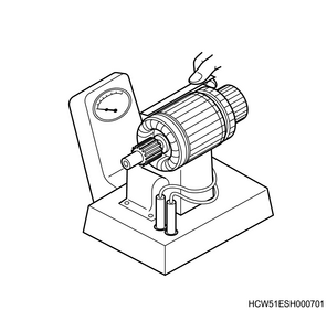
1) Inspect the armature for a short circuit.
Note
- A short circuit can be detected by rotating the armature in a growler with a steel strip, such as a hacksaw blade, held on the armature parallel to the shaft. The steel strip vibrates in the short-circuited area. A short circuit between the bars may be caused by brush dust.
2) Inspect the armature for a ground.
Note
- A ground in the armature can be detected using a self-powered test light or ohmmeter. Apply one probe of an ohmmeter or self-powered test light to the commutator segment, and the other probe to the armature core. If the light illuminates or an ohmmeter indicates continuity, the armature is grounded and must be replaced.
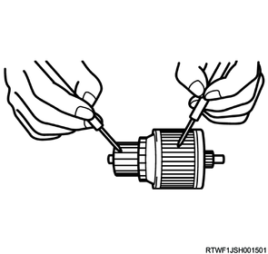
3) Inspect the armature for an open circuit.
Note
- Apply each probe of an ohmmeter or self-powered test light to 2 segments of the commutator. There must be continuity at any point in the commutator.
4. Magnetic switch assembly pull-in test
Caution
- Complete it in a short time (3 to 5 seconds) so that the coil will not burn.
1) Connect a jumper wire from the negative (-) side of the battery to the magnetic switch assembly terminal.
2) Connect a jumper wire from the positive (+) side of the battery to the magnetic switch assembly start terminal.
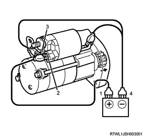
Legend
- Battery positive (+)
- Solenoid start terminal
- Solenoid motor terminal
- Battery negative (-)
5. Magnetic switch assembly hold-in test
Caution
- Complete it in a short time (3 to 5 seconds) so that the coil will not burn.
1) This test is performed in the same way as the pull-in test, except that a jumper wire is disconnected from the motor terminal of the magnetic switch assembly.
Note
- The pinion gear must be held in the hold-in position.
- If the pinion gear cannot be held in the hold position, replace the magnetic switch assembly.
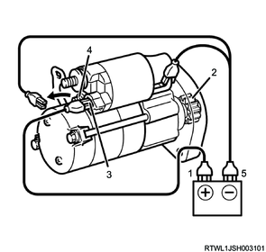
Legend
- Battery positive (+)
- Pinion gear
- Solenoid start terminal
- Solenoid motor terminal
- Battery negative (-)
6. Magnetic switch assembly return test
Caution
- Complete it in a short time (3 to 5 seconds) so that the coil will not burn.
1) Disconnect a jumper wire from the positive (+) side of the battery to the magnetic switch assembly start terminal.
Note
- The pinion gear must be returned to the correct position.
- If the pinion gear does not return to the correct position, replace the magnetic switch.
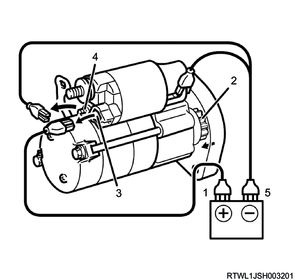
Legend
- Battery positive (+)
- Pinion gear
- Solenoid start terminal
- Solenoid motor terminal
- Battery negative (-)
7. Housing inspection
1) Inspect the housing assembly.
Note
- Inspect the bushing and oil seal, and replace the housing assembly if an abnormal condition is found.
8. Internal gear inspection
1) Inspect the internal gear.
2) Inspect the gear teeth, and replace the internal gear if abnormal wear or damage is found.
9. Shift lever inspection
1) Inspect the shift lever.
Note
- If the section which rubs the clutch is worn, the protrusion of the pinion is not in the correct position.
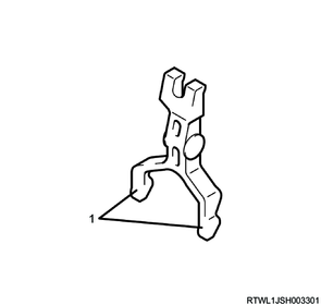
Legend
- Worn sections