1. Wireless access module safety information
When replacing the wireless access module, it is necessary to write the vehicle information into the new wireless access module.
When replacing the wireless access module, before removal, upload the old wireless access module data to a scan tool, referring to the following.
If communication with the scan tool cannot be established, remove as is.
During the replacement procedure, the same scan tool must be used from start to finish. If the scan tool is changed midway, information cannot be written correctly.
Make sure to check the vehicle specifications before replacing the wireless access module.
Use the following procedure when replacing or programming the wireless access module.
| If communication can be established with the old wireless access module. |
If communication cannot be established with the old wireless access module. |
|
| - |
Reset Wireless Access Module (WAM)*1 |
Reset Wireless Access Module (WAM)*1 |
| 1 |
Vehicle information upload |
- |
| 2 |
Wireless access module replacement |
Wireless access module replacement |
| 3 |
Transmission learning |
Transmission learning |
| 4 |
Vehicle information download |
Vehicle information programming |
| 5 |
Vehicle identification number (VIN) programming |
Vehicle identification number (VIN) programming |
| 6 |
Wireless Access Module (WAM) Registration |
Wireless Access Module (WAM) Registration |
| 7 |
Program Electronic KEY |
Program Electronic KEY |
| 8 |
ECU Lock |
ECU Lock |
| 9 |
DTC verification/clearing |
DTC verification/clearing |
Note
- *1: If reusing the wireless access module in another vehicle, perform "Reset Wireless Access Module (WAM)" in the original vehicle.
Caution
- Because "Reset Wireless Access Module (WAM)" cannot be performed in a new vehicle, be sure to perform "Reset Wireless Access Module (WAM)" in the original vehicle.
| If communication can be established with the old wireless access module. |
If communication cannot be established with the old wireless access module. |
|
| - |
Reset Wireless Access Module (WAM)*1 |
Reset Wireless Access Module (WAM)*1 |
| 1 |
Vehicle information upload |
- |
| 2 |
Wireless access module replacement |
Wireless access module replacement |
| 3 |
Vehicle information download |
Vehicle information programming |
| 4 |
Vehicle identification number (VIN) programming |
Vehicle identification number (VIN) programming |
| 5 |
Wireless Access Module (WAM) Registration |
Wireless Access Module (WAM) Registration |
| 6 |
Transponder Key Registration*2 |
Transponder Key Registration*2 |
| 7 |
Keyless Entry Key Registration*3 |
Keyless Entry Key Registration*3 |
| 8 |
ECU Lock |
ECU Lock |
| 9 |
DTC verification/clearing |
DTC verification/clearing |
Note
- *1: If reusing the wireless access module in another vehicle, perform "Reset Wireless Access Module (WAM)" in the original vehicle.
- *2: Perform only for models with immobilizer.
- *3: Perform only for models with keyless entry.
Caution
- Because "Reset Wireless Access Module (WAM)" cannot be performed in a new vehicle, be sure to perform "Reset Wireless Access Module (WAM)" in the original vehicle.
2. Wireless access module reset
1. Precautions
Caution
- When installing the wireless access module to the vehicle, it must be security linked to the steering lock assembly and ECM using the programming procedure. Once this linking has been performed, the wireless access module cannot be installed to any other vehicle. Before transferring (switching) to the vehicle in which the complaint originated, the resetting procedure must be performed in the original vehicle and the security linkages between all modules must be reset.
If the wireless access module to be replaced cannot establish communication with a scan tool, do not perform this operation.
2. Reset Wireless Access Module (WAM)
1) Connect the scan tool to the DLC.
2) Turn ON the ignition switch.
3) Select "Reset Wireless Access Module (WAM)" on the scan tool.
- Diagnostics > Body > WAM (Wireless Access Module) > Special Function > Wireless Access Module (WAM) > Reset Wireless Access Module (WAM)
4) Operate by following the on-screen instructions.
Caution
- Entering an incorrect security code causes a security wait time.
Note
- When turning the ignition switch ON and OFF by following the on-screen instructions, wait at least 5 seconds before turning it OFF or ON each time.
5) Turn OFF the ignition switch for 30 seconds.
6) Verify that the engine does not start with all the keys.
3. Wireless access module upload
1. Precautions
If replacing the wireless access module, this procedure is required.
If the wireless access module to be replaced cannot establish communication with a scan tool, do not perform this operation.
2. Vehicle information upload
1) Connect the scan tool to the DLC.
2) Turn ON the ignition switch.
3) Select "Upload Vehicle Configuration Data" on the scan tool.
- Diagnostics > Body > WAM (Wireless Access Module) > Programming > Upload Vehicle Configuration Data
4) Upload the vehicle data to a scan tool by following the on-screen instructions.
5) After completing the upload, turn off the scan tool.
6) Turn OFF the ignition switch.
4. SRS airbag safety information
1. Handling deployed airbag
Warning
- When handling the airbag, the safety precautions must be observed.
- The surface of the deployed airbag may contain a small amount of sodium hydroxide.
This is a byproduct of the deployment reaction, and may cause irritation if it comes in contact with the skin or eyes. - Be sure to wear gloves and safety glasses when handling an airbag after deployment.
- Wash hands with soap after handling.
Caution
- After the airbag is deployed, inspect for burning or melting caused by excessive heat, or any other problems.
- If the SRS coil is damaged, replace it.
2. Handling undeployed airbag assembly
Warning
- When transporting an undeployed airbag, make sure that the trim cover is facing away from your body.
- Never carry an airbag with pretensioner by holding the connector or harness.
- When placing an undeployed airbag, make sure to face the trim cover upward.
- Do not put any object on the steering wheel with the airbag surface facing downward.
- Not following this procedure may result in fire or injuries.
5. SRS airbag preparation
1. SRS deactivation
1) Set the ignition switch to LOCK and remove the key.
Note
- For models with the passive entry and start system, turn the power mode OFF.
2) Remove the SRS fuse from the fuse relay box.
3) Disconnect the battery cable from the battery negative terminal.
Caution
- After turning OFF the ignition switch (power mode for models with passive entry and start system), do not disconnect the battery cable within 3 minutes.
- If the battery cable is disconnected within 3 minutes, the vehicle electronic control system may malfunction.
- If the battery cable is disconnected, perform the setting of the front door power window switch with AUTO UP/AUTO DOWN function after connecting the battery negative terminal.
- After disconnecting the battery cable, do not perform work for approximately 15 seconds.
6. Front sill plate removal
1) Remove the front sill plate from the floor.
Regular cab, crew cab
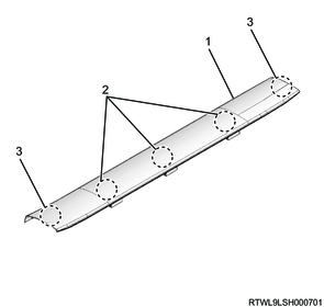
Legend
- Front sill plate
- Clip
- Claw section
Extend cab
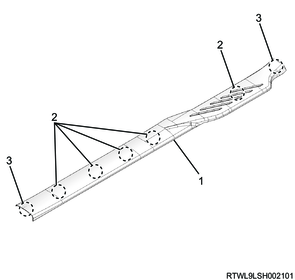
Legend
- Front sill plate
- Clip
- Claw section
7. Front door finisher removal
1) Remove the front door finisher from the body.
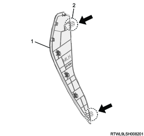
8. Front pillar trim cover removal
1. Models with assist grips
1) Remove the assist grip from the front pillar trim cover.
2) Remove the front pillar trim cover from the front pillar.
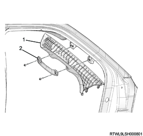
Legend
- Front pillar trim cover
- Assist grip
2. Models without assist grips
1) Remove the front pillar trim cover from the front pillar.
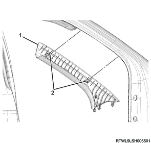
Legend
- Front pillar trim cover
- Clip
9. Audio and navigation system removal
1. Models equipped with display units
1) Remove the display unit as a set with the bezel from the instrument panel.
Caution
- When removing the display unit, place a cloth to the instrument panel.
- If a cloth is not used, the surface of the instrument panel may be damaged.
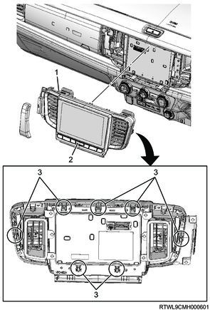
Legend
- Bezel
- Display unit
- Clip
2) Disconnect the connector from the display unit.
2. Models equipped with 2DIN audio
1) Remove the 2DIN audio as a set with the bezel from the instrument panel.
Caution
- When removing the 2DIN audio, place a cloth to the instrument panel.
- If a cloth is not used, the surface of the instrument panel may be damaged.
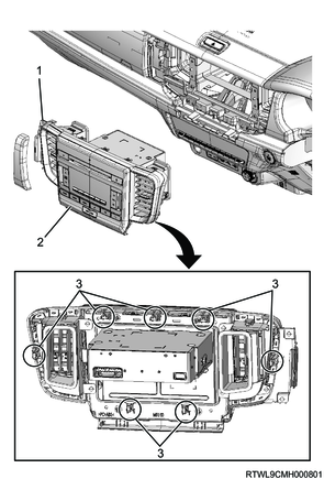
Legend
- Bezel
- 2DIN audio
- Clip
2) Disconnect the connector from the 2DIN audio.
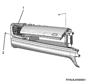
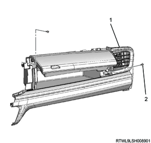
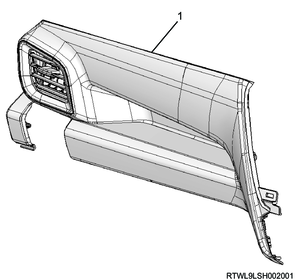
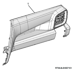
10. Instrument panel passenger-side upper cover removal
1) Remove the instrument panel passenger-side upper cover from the instrument panel.
High grade type (RHD)
Legend
- Instrument panel passenger-side upper cover
- Screw
High grade type (LHD)
Legend
- Instrument panel passenger-side upper cover
- Screw
Low grade type (RHD)
Legend
- Instrument panel passenger-side upper cover
Low grade type (LHD)
Legend
- Instrument panel passenger-side upper cover
11. Meter cluster removal
1) Remove the meter cluster from the instrument panel.
RHD
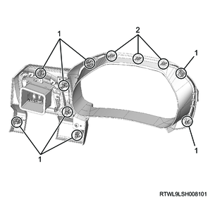
Legend
- Clip
- Claw section
LHD
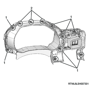
Legend
- Clip
- Claw section
12. Instrument panel removal
1) Remove the side cover from the instrument panel.
Legend
- Side cover
- Claw section
2) Disconnect the passenger airbag from the reinforcement.
3) Disconnect the connector from the instrument panel (upper side).
4) Remove the instrument panel (upper side) from the instrument panel (lower side).
High grade type
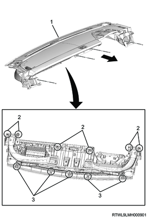
Legend
- Instrument panel (Upper side)
- Clip
- Claw section
Low grade type
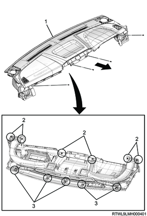
Legend
- Instrument panel (Upper side)
- Clip
- Claw section
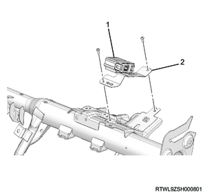
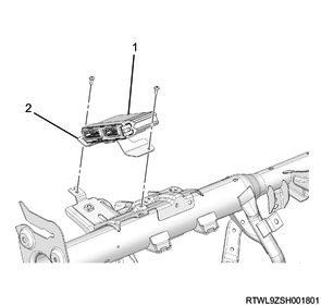
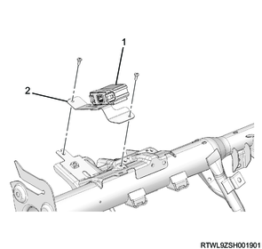
13. Wireless access module removal
1) Remove the wireless access module as a set with the bracket from the reinforcement.
Models with passive entry and start system (RHD)
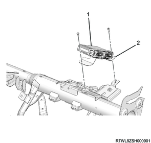
Legend
- Wireless access module
- Bracket
Models without passive entry and start system (RHD)
Legend
- Wireless access module
- Bracket
Models with passive entry and start system (LHD)
Legend
- Wireless access module
- Bracket
Models without passive entry and start system (LHD)
Legend
- Wireless access module
- Bracket
2) Remove the wireless access module from the bracket.