1. Component views
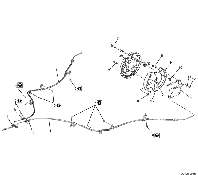
Parking brake (2WD (Except high ride suspension specifications))

Part name
- Equalizer
- T-end
- Parking brake cable nut
- Retainer
- Parking brake cable
- Parking brake cable bolt
- Nut
- Shoe holder pin
- Pin
- Brake shoe
- Shoe holding spring
- Lever washer
- Retainer
- parking lever
- Upper spring
- Lower spring
- Adjust lever ring
- Adjust lever
Tightening torque
3: 19.7 to 29.6 N⋅m {2.01 to 3.02 kgf⋅m / 14.5 to 21.8 lb⋅ft}
6: 4.60 to 8.50 N⋅m {0.470 to 0.870 kgf⋅m / 40.7 to 75.2 lb⋅in}
7: 8.10 to 12.2 N⋅m {0.830 to 1.24 kgf⋅m / 71.7 to 108.0 lb⋅in}
Parking brake (2WD (High ride suspension specifications), 4WD)
Part name
- Equalizer
- Parking brake cable nut
- Retainer
- Parking brake cable
- Parking brake cable bolt
- Nut
- Shoe holder pin
- Pin
- Brake shoe
- Shoe holding spring
- Lever washer
- Retainer
- parking lever
- Upper spring
- Lower spring
- Adjust lever ring
- Adjust lever
Tightening torque
2: 19.7 to 29.6 N⋅m {2.01 to 3.02 kgf⋅m / 14.5 to 21.8 lb⋅ft}
5: 4.60 to 8.50 N⋅m {0.470 to 0.870 kgf⋅m / 40.7 to 75.2 lb⋅in}
6: 19.7 to 29.6 N⋅m {2.01 to 3.02 kgf⋅m / 14.5 to 21.8 lb⋅ft}
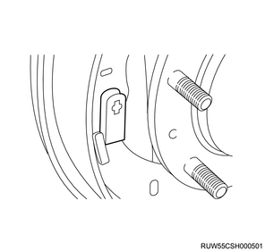
2. Brake shoe installation
1) Apply grease to the brake shoe fitting section and back plate sliding section.

Legend
- Back plate sliding section
- Brake shoe fitting section
2) Install the brake shoe to the back plate.
Caution
- Do not damage the wheel cylinder dust cover.
- Make sure the wheel cylinder piston does not shoot out.
3) Install the lower spring to the brake shoe.
4) Install the upper spring to the adjuster.
5) Install the adjuster and upper spring to the brake shoe.
6) Install the following parts to the front brake shoe.
- Adjust lever
- Adjust lever ring
Caution
- Do not reuse the adjust lever ring.
7) Install the adjust lever spring to the adjust lever and brake shoe.
8) Install the shoe holder pin to the brake shoe.
Caution
- Do not reuse the shoe holder pin.
9) Install the shoe holding spring to the shoe holder pin.
Caution
- Do not reuse the shoe holding spring.
3. Parking brake cable installation
1) Install the parking brake cable bracket to the frame.
Tightening torque: 4.60 to 8.50 N⋅m {0.470 to 0.870 kgf⋅m / 40.7 to 75.2 lb⋅in}
4. Parking brake cable connect
1. Connection to parking brake lever
1) Apply multi-purpose grease to the connection portion of the T-end of the parking brake cable and the equalizer.
2) Install the T-end of the parking brake cable to the equalizer of the front parking brake cable.
3) Install the floor side retainer to the floor.
Tightening torque: 19.7 to 29.6 N⋅m {2.01 to 3.02 kgf⋅m / 14.5 to 21.8 lb⋅ft}
2. Connection to brake
1) Install the parking brake cable to the back plate.
Note
- Install the inner cable to the back plate hole. Then install the case cap of the outer cable to the back plate.
2) Install the parking brake cable to the parking lever.
3. Connection to leaf spring
1) Install the parking brake cable to the leaf spring bracket.
Tightening torque: 8.10 to 12.2 N⋅m {0.830 to 1.24 kgf⋅m / 71.7 to 108.0 lb⋅in} 2WD (Except high ride suspension specifications)
Tightening torque: 19.7 to 29.6 N⋅m {2.01 to 3.02 kgf⋅m / 14.5 to 21.8 lb⋅ft} 2WD (High ride suspension specifications), 4WD
5. Brake drum installation
1) Install the brake drum to the rear axle shaft.
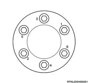
6. Disc wheel installation
1. Models with aluminum wheels
1) Temporarily tighten the disc wheel to the vehicle.
2) Lower vehicle.
3) Final tighten the wheel nut in the order shown in the diagram.
Tightening torque: 120 N⋅m {12 kgf⋅m / 87 lb⋅ft}
Caution
- After completing installation, make sure to further tighten the wheel nuts to the specified torque after the vehicle has been driven a distance exceeding the standard value.
Standard: 50 to 100 km { 31 to 62 mile }
4) Install the wheel cap to the disc wheel.
Note
- For models with 18-inch aluminum wheels, align the wheel cap groove with the air valve before installing.
5) Check that the surfaces of the wheel cap and wheel are flat.
Note
- If the surfaces are not flat, the wheel cap may fall off.
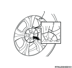
Legend
- Valve
- Wheel cap groove
2. Models with steel wheels
1) Temporarily tighten the disc wheel and wheel cap to the vehicle.
2) Lower vehicle.
3) Final tighten the wheel nut in the order shown in the diagram.
Tightening torque: 120 N⋅m {12 kgf⋅m / 87 lb⋅ft}
Caution
- After completing installation, make sure to further tighten the wheel nuts to the specified torque after the vehicle has been driven a distance exceeding the standard value.
Standard: 50 to 100 km { 31 to 62 mile }
7. Rear drum brake adjustment
1. Rear drum brake lining gap adjustment (Except after overhaul)
All brakes are automatic adjustment type. The lining gap is automatically adjusted by repeatedly depressing the brake pedal.
1) Repeatedly depress and release the brake pedal until the click of the auto adjuster is not heard.
2) When the clicking sound can no longer be heard, depress the brake pedal 10 times to make sure that there is no stroke variation.
2. Rear drum brake lining gap adjustment (After overhaul, bench seat specifications)
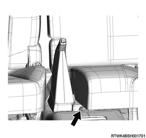
1) Release the parking brake lever by moving it to the position where it is completely released.
2) Loosen the adjust nut using a wrench.
3) Repeatedly depress and release the brake pedal until the click of the auto adjuster is not heard.
Note
- If the clearance between the brake drum and the lining is adjusted to 0.5 mm {0.020 in}, the number of times of depressing the brake pedal can be reduced.
4) When the clicking sound can no longer be heard, depress the brake pedal 10 times to make sure that there is no stroke variation.
5) Remove the cover from the back plate.
6) Measure the gap between the brake drum and brake shoe.
Standard: 0.25 to 0.40 mm { 0.0098 to 0.0157 in } Lining clearance
Note
- If it is outside the standard range, inspect the adjuster.
7) Turn the adjust nut so that the parking brake lever is pulled up 6 to 9 notches when the lever is pulled up with the force of 294 N {30 kg/66 lb}.
Caution
- Make sure the brake does not drag.
RHD models (LHD models are opposite)
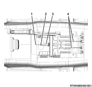
Legend
- Equalizer
- Adjust nut
- Spacer
- Parking brake cable
3. Rear drum brake lining gap adjustment (After overhaul, center console specifications)
1) Release the parking brake lever by moving it to the position where it is completely released.
2) Loosen the adjust nut using a wrench.
3) Repeatedly depress and release the brake pedal until the click of the auto adjuster is not heard.
Note
- If the clearance between the brake drum and the lining is adjusted to 0.5 mm {0.020 in}, the number of times of depressing the brake pedal can be reduced.
4) When the clicking sound can no longer be heard, depress the brake pedal 10 times to make sure that there is no stroke variation.
5) Remove the cover from the back plate.
6) Measure the gap between the brake drum and brake shoe.
Standard: 0.25 to 0.40 mm { 0.0098 to 0.0157 in } Lining clearance
Note
- If it is outside the standard range, inspect the adjuster.
7) Turn the adjust nut so that the parking brake lever is pulled up 6 to 9 notches when the lever is pulled up with the force of 294 N {30 kg/66 lb}.
Caution
- Make sure the brake does not drag.
RHD models (LHD models are opposite)
Legend
- Equalizer
- Adjust nut
- Spacer
- Parking brake cable
8. Console box installation
1. Models with console boxes
Refer to "9.Body, Cab, Accessories 9L.Exterior, Interior Trim console box installation".