1. Introduction to the trouble diagnosis of restraint
1. DTC
Read the flash code by observing the flashes of the SRS airbag warning light, or observe the DTC information with a scan tool.
1) Active DTC (DTC currently set)
Malfunctions that have been detected. Active codes are recorded in the RAM (random access memory).
2) History DTC (DTC set in the past)
History of all uncleared malfunctions (Reoccurring malfunctions, and malfunctions detected in the current ignition cycle). History codes are recorded in the EEPROM.
Before performing diagnosis, perform the Diagnostic system check-SRS controls. Whether the SRS airbag warning light operates normally can be checked by the Diagnostic system check-SRS controls.
2. Overview of system diagnostic method
The system diagnostic method is a standardized method for repairing all electrical/electronic (E/E) systems. It is always used to solve problems with E/E systems and is the starting point when a repair is required. The following steps indicate how to proceed through the diagnosis.
1) Verify the customer's complaint.
In order to verify the customer's complaint, it is necessary to know how the system normally operates.
2) Perform a preliminary inspection.
- Overall visual inspection
- Maintenance history review
- Detection of abnormal noise and odor
- Collection of DTCs and system data using a scan tool
3) Check for related Service Bulletins.
Check Service bulletins, maintenance manuals, etc.
4) If a DTC is set
Perform the repair accurately according to the specified DTC diagnosis.
5) If no DTC is set
Refer to Diagnosis by symptom, and inspect.
6) If there are no applicable symptoms
- Investigate the complaint in detail.
- Create a diagnosis plan.
- Check the operation principles based on the wiring diagram and maintenance information.
When repair history for similar cases is available, request technical assistance. Check again for related Service Bulletins.
7) Intermittent conditions
Failures that do not always appear are referred to as being intermittent. Perform the following in order to resolve intermittent conditions.
- Observe the DTC information and the SRS data.
- Verify the symptoms and conditions described by the customer.
- Use a check sheet or another method to check the circuits or electrical system components.
8) If no failures are detected
This situation indicates that the vehicle is operating normally. The condition reported by the customer may be normal. Check the customer complaint by comparing to another vehicle that is operating normally. However, depending on the condition, it may be an intermittent condition. Before returning the vehicle, check the complaint under the conditions given by the customer.
9) Investigate the complaint again.
If the complaint cannot be adequately detected or determined, it is necessary to perform the diagnosis again. As stated above in regard to "Intermittent conditions", the complaint may be intermittent or may be a normal condition.
10) Perform the operation verification.
Verify that the vehicle is operating normally and that the symptom has been resolved. This includes a road test and other methods to verify that the complaint has been resolved under the following conditions.
- Verify by testing under the conditions given by the customer.
- If a DTC was set, verify that the malfunction has been repaired by duplicating the conditions when the DTC was set while observing the scan tool data.
3. Diagnostic procedure
Warning
- When performing maintenance of the SRS, in order to prevent the SRS airbag and the seat belt with pretensioner from activating, do not use inspection devices other than those specified in this manual. If inspection devices other than those specified in this manual are used, damage due to unnecessary activation of the SRS airbag or the seat belt with pretensioner may occur.
The diagnostic procedure is meant to detect SRS problems with the objective of making repairs. The procedure for quickly detecting SRS problems and effectively repairing is as follows. Skipping these procedures may result in longer diagnosis time, incorrect diagnosis, or replacement of wrong parts.
1) Perform a preliminary inspection.
The following items must always be performed at the start of a diagnosis.
- Overall visual inspection for poor connections at the terminals, wires, etc., and for evidence of the SRS control unit coming into contact with water (coffee, juice, etc.)
- Maintenance history review
- Check for abnormal noise and odor
2) Perform the Diagnostic system check - SRS controls.
- Verify that the SRS airbag warning light operates properly.
- Verify that communication can be established with the SRS control unit using a scan tool.
- Read the flash code by observing the flashes of the SRS airbag warning light, or observe the DTC information with a scan tool.
3) Go to the appropriate diagnosis procedure according to the instructions from the Diagnostic system check-SRS controls.
Skipping these procedures may result in longer diagnosis time, incorrect diagnosis, or replacement of wrong parts.
4) After performing the repair or diagnosis procedures, repeatedly perform the Diagnostic system check - SRS controls.
It is possible to check whether repairs have been performed properly and whether there are any other problems.
2. Diagnostic trouble codes (DTCs)
1. Regarding DTCs
The SRS control unit records any DTC that is set.
1) Active DTC (DTC currently set)
Failure detected in the current ignition cycle.
2) History DTC (DTC set in the past)
History of all uncleared malfunctions (Reoccurring malfunctions, and malfunctions detected in the current ignition cycle).
2. Required basic knowledge
A basic knowledge is required to use the service manual. The diagnosis may not be completed without this knowledge. Also, the SRS airbag and the seat belt with pretensioner may be unnecessarily activated. Read and understand all of the precautions in the service manual as well as on the warning labels attached to SRS components.
3. Basic electrical circuits
It is necessary to understand basic theories on electricity, including serial circuits and parallel circuits, and voltage drops in the series resistance. It is also necessary to understand the meanings of voltage (volt), current (ampere), and resistance (ohm), and what happens in the circuit if an open circuit or short circuit occurs. Make sure to read and understand the wiring diagram.
4. Flash code and DTC reading method
The flash codes are displayed through the flashing of the SRS airbag warning light when pins 13 and 4 or 5 of the data link connector (DLC) are short-circuited. (Only the presence of the trouble code is displayed for past trouble codes, and no specific failure content is displayed.) All DTCs (current and past DTCs) can be read using the scan tool.
5. Flash code diagnosis
The flash codes are displayed through the flashing of the SRS airbag warning light when pins 13 and 4 or 5 of the data link connector (DLC) are short-circuited. Turn ON the ignition switch, and perform the diagnosis. The SRS control unit displays flash codes by flashing the SRS airbag warning light.
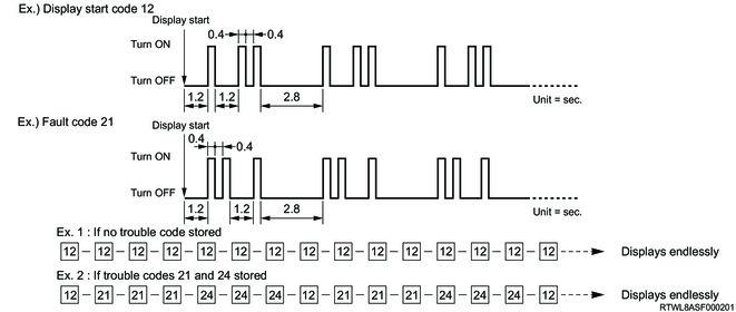
In flashing mode, the light is OFF for the initial 1.2 seconds, then code "12" flashes only once. The illuminating time is 0.4 seconds and turning OFF time is 0.4 seconds, OFF time between the tens digit and the ones digit is 1.2 seconds, and OFF time between faults is 2.8 seconds. If there are multiple DTCs, each code is displayed 3 times. After all the codes are displayed, each code is repeatedly displayed until the short circuit between pins 13 and 4 or 5 of the DLC is removed.
There are two special flash codes (code 12 and code 13). Code 12 indicates that the warning light is in the flashing mode. If no current failure or past failure is set, the SRS control unit displays code 12 until the short circuit between pins 13 and 4 or 5 of the DLC is removed. Code 13 is displayed when any past failures are set.
A scan tool is required to read the contents of past failures. If a scan tool is used, leave pins 13 and 4 or 5 of the DLC open.
6. If a DTC is set
After flash code 12 is displayed once, the stored DTCs are displayed 3 times. When 2 or more DTCs have been stored, the DTCs are displayed 3 times, each in ascending order of DTC number. After displaying all codes, the codes will be displayed again starting with flash code No. 12. This display continues while DLC pins 13 and 4 or 5 are short-circuited.
7. DTC clearing
A DTC cannot be cleared without using a scan tool. However, if DTC 1900[00], B1901[00], B1902[00], B1903[00], B190F[00], or B1E17[00] is set, the SRS control unit must be replaced because the DTC cannot be cleared.
3. Inspection standards for repairing the airbag system
| Part name |
Inspection standards |
Standards for replacing parts |
|
| SRS parts |
SRS airbag |
When a collision occurs When trouble occurs When conducting a periodic inspection |
The SRS airbag was deployed due to a collision. Damage or cracks are found on the pad surface. Flaws or cracks are found in the connector. A cut or coating breakage is found in the harness. |
| SRS control unit |
When a collision occurs When trouble occurs When conducting a periodic inspection |
The SRS airbag was deployed due to a collision. Flaws, cracking, or deformation is found in the SRS control unit body. Flaws or cracks are found in the connector. As a result of the diagnosis, instructions to replace the SRS control unit were given. The area around the connector was splashed with water. |
|
| SRS coil |
When a collision occurs When trouble occurs When conducting a periodic inspection |
The SRS airbag was deployed due to a collision. Flaws, cracks, or deformation is found on the case body or bracket. As a result of the diagnosis, instructions to replace the part were given. |
|
| Seat belt with pretensioner |
When a collision occurs When trouble occurs When conducting a periodic inspection |
The seat belt with pretensioner was deployed due to a collision. Flaws, cracks, or deformation is found on the case body or bracket. As a result of the diagnosis, instructions to replace the part were given. |
|
| Front airbag sensor |
When a collision occurs When trouble occurs When conducting a periodic inspection |
Flaws, cracks, or deformation are found in the front airbag sensor body. Flaws, cracks, or deformation are found in the connector. As a result of the diagnosis made using the workshop manual, instructions to replace the part were given. |
|
| Floor side airbag sensor |
When a collision occurs When trouble occurs When conducting a periodic inspection |
Flaws, cracks, or deformation are found in the floor side airbag sensor body. Flaws, cracks, or deformation are found in the connector. As a result of the trouble diagnosis made using the workshop manual, instructions to replace the part were given. |
|
| Door side airbag sensor |
When a collision occurs When trouble occurs When conducting a periodic inspection |
Flaws, cracks, or deformation are found in the door side airbag sensor body. Flaws, cracks, or deformation are found in the connector. As a result of the diagnosis made using the workshop manual, instructions to replace the part were given. |
|
| Rear side airbag sensor |
When a collision occurs When trouble occurs When conducting a periodic inspection |
Flaws, cracks, or deformation are found in the rear side airbag sensor body. Flaws, cracks, or deformation are found in the connector. As a result of the trouble diagnosis made using the workshop manual, instructions to replace the part were given. |
|
| Passenger side SRS airbag indicator |
When a collision occurs When trouble occurs When conducting a periodic inspection |
Flaws, cracks, or deformation are found in the passenger side SRS airbag indicator body. Flaws, cracks, or deformation are found in the connector. As a result of the trouble diagnosis made using the workshop manual, instructions to replace the part were given. |
|
| Passenger side SRS airbag cut off switch |
When a collision occurs When trouble occurs When conducting a periodic inspection |
Flaws, cracks, or deformation are found in the passenger side SRS airbag cut off switch body. Flaws, cracks, or deformation are found in the connector. As a result of the trouble diagnosis made using the workshop manual, instructions to replace the part were given. |
|
| SRS harness |
When a collision occurs When trouble occurs When conducting a periodic inspection |
A cut or coating breakage is found in the wire harness for the SRS circuit. Flaws or cracks are found in the connector. As a result of the diagnosis, instructions to replace the part were given. |
|
| Steering wheel |
When a collision occurs |
The wheel section is not perfectly round. The bracket is deformed. When the new SRS airbag was installed, there was interference between the pad and the steering wheel, resulting in the clearance not being even. |
|
| Related parts |
Steering column |
When a collision occurs |
The shaft and bracket supporting the shaft are deformed. Tilting operations are not smooth. |
| Instrument panel, crossbeams, covers, etc. |
When a collision occurs |
A dent, bend, flaw, crack, or deformation is found. (Replace seat belts that are activated in collisions.) |
|
| Glove box |
|||
| Seat |
|||
| Seat belt |
|||
| Windshield glass |
|||
| Installation section of the mating portion |
When a collision occurs |
When a dent, bend, flaw, crack, or deformation is found, repair the part or replace it with a new one. If there is looseness in the installation section, tighten it to the specified torque. |
|
1. Regarding inspection standards
1) When a collision occurs
Any type of collision has occurred, regardless of whether the SRS airbag was deployed.
2) When trouble occurs
The SRS airbag warning light does not illuminate for 6 seconds or remains ON.